

Tank Device For Storing A Liquid Medium That Reduces Pollutant Levels
- Summary
- Abstract
- Description
- Claims
- Application Information
AI Technical Summary
Benefits of technology
Problems solved by technology
Method used
Image

Examples
first embodiment
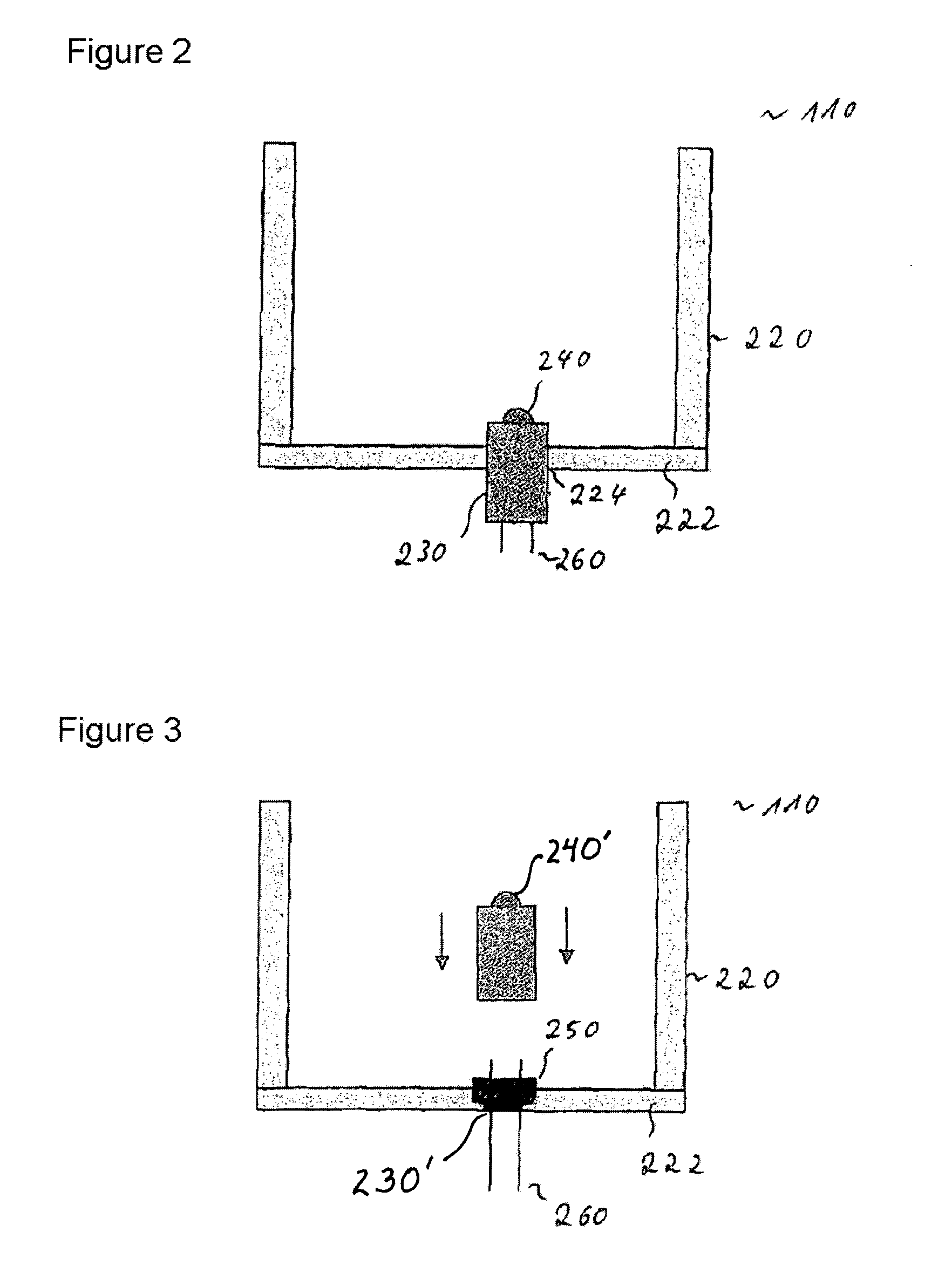
[0031]FIG. 2 shows the tank device. The tank device 110 comprises a container 220 for storing the reducing agent, having a container wall 222, which comprises a first plastic, at least in a first contact area. The tank device 110 furthermore comprises a support element 230, which is arranged in an aperture 224 in the container wall 222 and has an overmolding comprising a second plastic, at least in a second contact area, which is coupled to the first contact area of the container wall 222 in a substantially liquid-tight manner in the second contact area. The first and the second plastic can comprise substantially the same chemical components. The first plastic and the second plastic can comprise polyethylene and, in particular, can be composed of polyethylene, for example.
[0032]The aperture 224 in which the support element 230 is arranged is arranged in spatial proximity to a discharge opening of the tank device 110, for example. The aperture 224 is preferably arranged in a bottom w...
second embodiment
[0034]FIG. 3 shows the tank device. In comparison with the embodiment shown in FIG. 2, the support element 230′ in this case has a locking device 250 for the mechanical and / or electrical coupling of a subassembly 240′. The subassembly can comprise an ultrasonic sensor, for example.
[0035]The tank device 110 can have one or more such support elements. The support elements 230, 230′ can be of different designs. The respective support element 230, 230′ can comprise a sensor device 240 or a locking device 250 or a sensor device 240′ and a locking device 250, for example.
PUM
 Abstract
Description
Claims
Application Information