Apparatus for controlling power factor compensation in inverter control circuit and method thereof

a technology of power factor compensation and control circuit, which is applied in the direction of dynamo-electric converter control, instruments, heating types, etc., can solve the problems of reducing the endurance of null power, limiting the power factor enhancement, and wasting power consumption

Inactive Publication Date: 2006-05-23
LG ELECTRONICS INC
View PDF3 Cites 48 Cited by
  • Summary
  • Abstract
  • Description
  • Claims
  • Application Information

AI Technical Summary

Benefits of technology

[0029]Another object of the present invention is to provide an apparatus for controlling power factor compensation and method thereof, by which a turn-on timing point of a power factor compensation switch can be adaptively controlled according to a load size in a manner of controlling a time delay value for the turn-on timing point of a power factor compensation switch in inverse proportion to the load size.
[0032]A further object of the present invention is to provide an apparatus for controlling power factor compensation and method thereof, in which a time delay value for a turn-on timing point of a power factor compensation switch can be lowered or raised if a current DC link voltage higher or lower than a target DC link voltage and by which a power factor can be enhanced via a re-established time delay value for the turn-on timing point of the power factor compensation switch according to lapse of a load driving time.

Problems solved by technology

As harmonic hindrance accelerates degradation of various power devices, their endurances are shortened, the danger of fire due to overheating and the like is aggravated, and null power increases to waste power consumption.
However, since the switch of the power factor compensator is turned on at the zero crossing timing point of the power voltage, the related art puts limitation on the power factor enhancement.
Hence, it is unable to uniformly control the power factor for a wide operational range of the load, whereby the power factor enhancement is limited.
Moreover, if the DC voltage needed by the circuit is low, it may be difficult to control the DC voltage uniformly.

Method used


Image

  • Apparatus for controlling power factor compensation in inverter control circuit and method thereof
  • Apparatus for controlling power factor compensation in inverter control circuit and method thereof
  • Apparatus for controlling power factor compensation in inverter control circuit and method thereof

Examples


Embodiment Construction

[0046]Reference will now be made in detail to the preferred embodiments of the present invention, examples of which are illustrated in the accompanying drawings. Wherever possible, the same reference numbers will be used throughout the drawings to refer to the same or like parts.

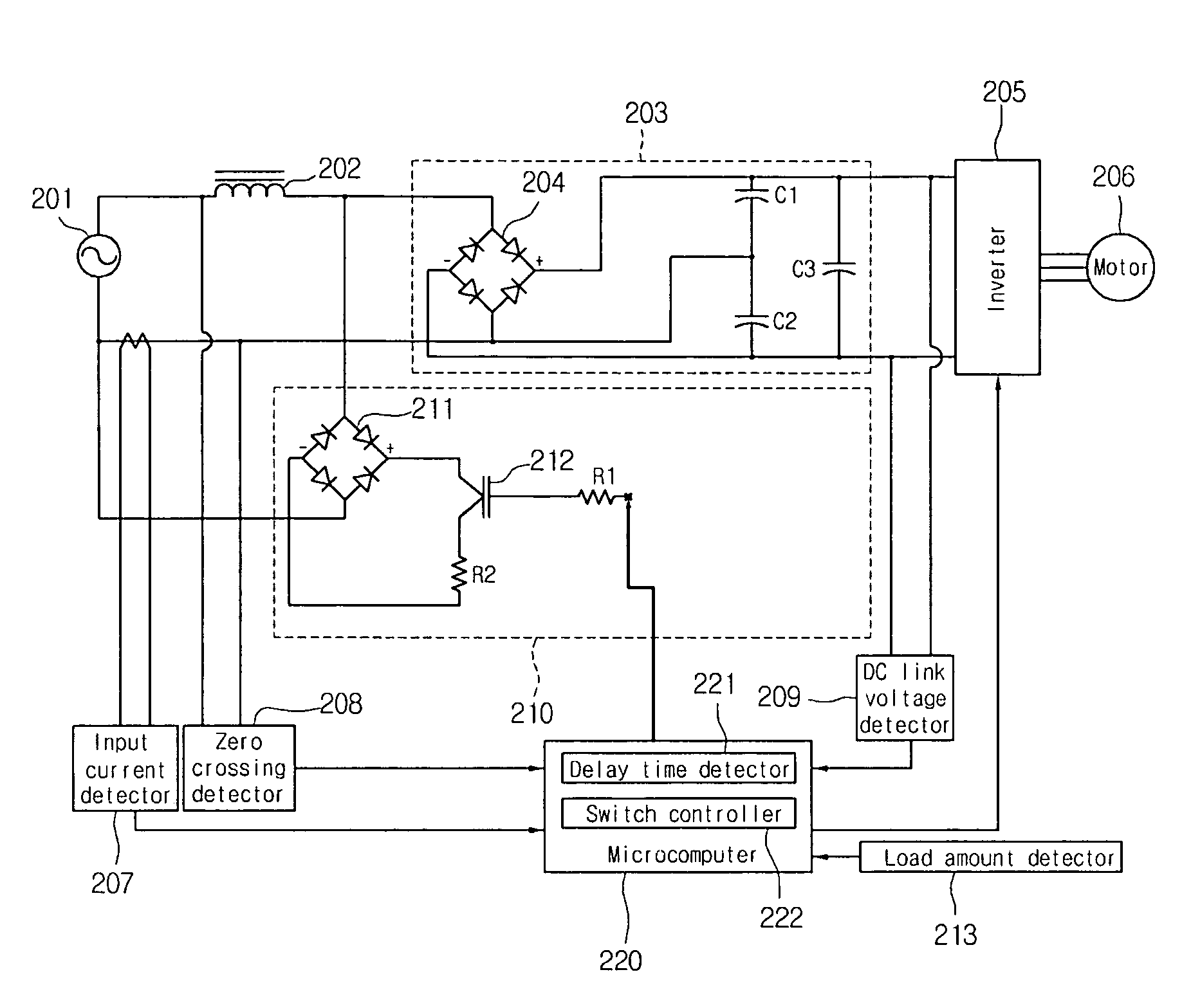
[0047]FIG. 4 shows a configuration of an inverter control circuit according to an embodiment of the present invention.

[0048]Referring to FIG. 4, an inverter control circuit according to the present invention includes a reactor 202 displaying reactance passing a specific frequency among an inputted AC power 201, a rectifier 203 having a bridge diode 204 and smoothing capacitors C1 to C3 to convert AC power to DC power, an inverter 205 inverting DC power to AC power to drive a motor 206, an input current detector 207 detecting an input current, a zero crossing detector 208 detecting a zero crossing point of the inputted AC power 201, a DC link voltage detector 209 detecting a rectified DC voltage, a load amoun...


PUM


Abstract

The present invention provides an apparatus for controlling power factor compensation and method thereof, in which a turn-on timing point of a power factor compensation switch is delayed by a prescribed time from a zero crossing timing point to enhance a power factor. The present invention includes periodically detecting a zero crossing time point of an inputted voltage, turning on the power factor compensation switch if a turn-on time point of the power factor compensation switch set to a time point delayed by a prescribed time from the detected zero crossing time of the inputted voltage is reached, and turning off the power factor compensation switch if a prescribed time passes after turning on the power factor compensation switch.

Description

BACKGROUND OF THE INVENTION[0001]1. Field of the Invention[0002]The present invention relates to an inverter control circuit, and more particularly, to an apparatus for controlling power factor compensation and method thereof, in which a delay of a turn-on timing point of a power factor compensation switch is controlled to enhance a power factor.[0003]2. Discussion of the Related Art[0004]Generally, an air conditioner is a home appliance for maintaining a room air optimal to its usage and purpose. For instance, the air conditioner controls the room air to provide a cooling state to a room in summer or a heating state to the room in winter. The air conditioner adjusts humidity within the room. And, the air conditioner refines the room air into a clean and pleasant state.[0005]As convenient home appliances such as the air conditioner propagate to become popular in use, the user's demand for high energy efficiency, performance enhancement, and convenience of the products rises.[0006]Mo...

Claims


Application Information

Patent Timeline
Patent Type & Authority Patents(United States)
IPC IPC(8): G05F1/70H02M7/12F24F11/02H02M1/12H02M1/42H02M7/42H02M7/44H02P23/26H02P27/06
CPCH02M1/12H02M1/4208Y02B70/126Y02B70/10F24F11/88
Inventor CHIN, SIM WONLIM, SUNG YEOBHUH, DEOK
Owner LG ELECTRONICS INC
Why Eureka
Try Eureka