Key control system using separated ID and location detection mechanisms

a technology of location detection and key control system, applied in the field of object control system, can solve problems such as inability to know, system cannot identify specific locations, and system is not completely secur

Inactive Publication Date: 2006-05-23
DEUT BANK AG NEW YORK BRANCH
View PDF72 Cites 24 Cited by
  • Summary
  • Abstract
  • Description
  • Claims
  • Application Information

AI Technical Summary

Problems solved by technology

Thus, the system is not completely secure.
In these systems, the controller knows that a tag is in the receptacle but cannot know the particular slot of the receptacle occupied by the tag.
The shortcomings of such a system include the fact that the system can not identify the specific location of each tag within the receptacle.
In these systems, as well, the controller can never identify the specific location of a tag within the receptacle.

Method used


Image

  • Key control system using separated ID and location detection mechanisms
  • Key control system using separated ID and location detection mechanisms
  • Key control system using separated ID and location detection mechanisms

Examples


Embodiment Construction

[0025]The separation of the identification and location detection functions of the present invention is described herein in the context of a system that utilizes RFID tags. It is possible using the concepts of the present invention to construct equivalent systems using one-wire memory devices and / or other memory devices.

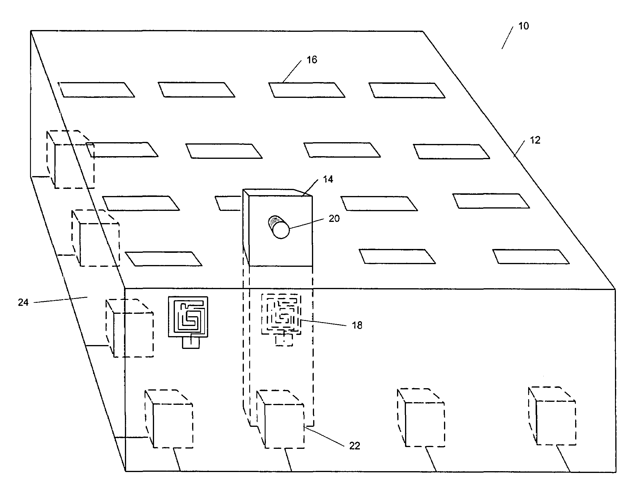
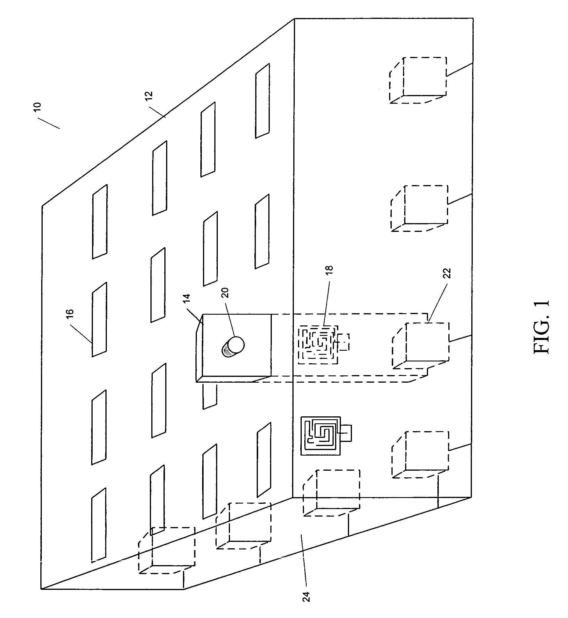
[0026]A representation of a key control assembly having separated identification and location detection functions is illustrated in FIG. 1. The key control assembly 10 is a portion of a key control system. The key control assembly 10 includes a key control enclosure 12. The key tags 14 are inserted through narrow key-tag slots 16 in the top tray 15 of the enclosure 12. The portion of the key tag 14 that is inside the enclosure contains an RFID tag 18. The keys are attached, via key attachment 20, to the portion of the key tags that are outside the key control enclosure 12. Presence detectors 22 are placed on a backplane 24 on the bottom of the enclosure 12. Correspon...


PUM


Abstract

An object control and tracking system and related methods using separate object identification and location detection mechanisms for objects, such as keys, that are maintained in a secure enclosure, such as a key drawer. A plurality of object slots are located on the top tray of the enclosure to receive object tags that include both an RFID tag and an object to be tracked. The objects (e.g., keys) are attached to a portion of the object tags that are outside of the enclosure. Presence detectors are used to determine if an object tag is present in the corresponding slot of the enclosure. RFID sensors located on opposite interior side walls of the enclosure interrogate each RFID tag to determine the presence of each RFID tag within the enclosure. The object control and tracking system includes a controller, a memory for storing an object control database, and related processing logic operating on the controller to control scanning of the presence detectors to determine an object tag's presence in a corresponding slot, to identify each object present in the enclosure and to compare the identified objects with an object control database to determine each object removed or replaced since the previous database update.

Description

CROSS-REFERENCE TO RELATED APPLICATION[0001]The present patent application is a continuation of U.S. patent application Ser. No. 10 / 133,130, filed Apr. 26, 2002 now U.S. Pat. No. 6,812,838; which application is a formalization of a previously filed, co-pending provisional patent application entitled “Key Control System that Uses Separated ID and Location Detection Mechanisms,” filed Apr. 26, 2001, as U.S. patent application Ser. No. 60 / 286,760 by the inventor named in this patent application and claims the benefit of the filing date of the cited provisional patent application, according to the statutes and rules governing provisional patent applications, particularly 35 USC § 119(e)(1) and 37 CFR §§ 1.789(a)(4) and (a)(5). The specification and drawings of the provisional patent application are specifically incorporated herein by reference.BACKGROUND OF THE INVENTION[0002]The present invention is generally related to controlling and tracking access to various types of objects. More ...

Claims


Application Information

Patent Timeline
Patent Type & Authority Patents(United States)
IPC IPC(8): G08B13/14G06K17/00
CPCG06K7/10079G06K17/00G08B13/2417G08B13/2462G07C2009/00936G06K2017/0045A47G29/10
Inventor MALONEY, WILLIAM C.
Owner DEUT BANK AG NEW YORK BRANCH
Why Eureka
Try Eureka