
Image pickup device and cover plate with conductive film layer

a pickup device and conductive film technology, applied in the field of transparent cover plates, can solve the problems of limiting design flexibility along the optical axis, affecting the quality of the image, and requiring a relatively large space for the filter, so as to prevent dust collecting

Inactive Publication Date: 2006-05-23
RICOH IMAGING COMPANY
View PDF13 Cites 7 Cited by
  • Summary
  • Abstract
  • Description
  • Claims
  • Application Information

AI Technical Summary

Benefits of technology

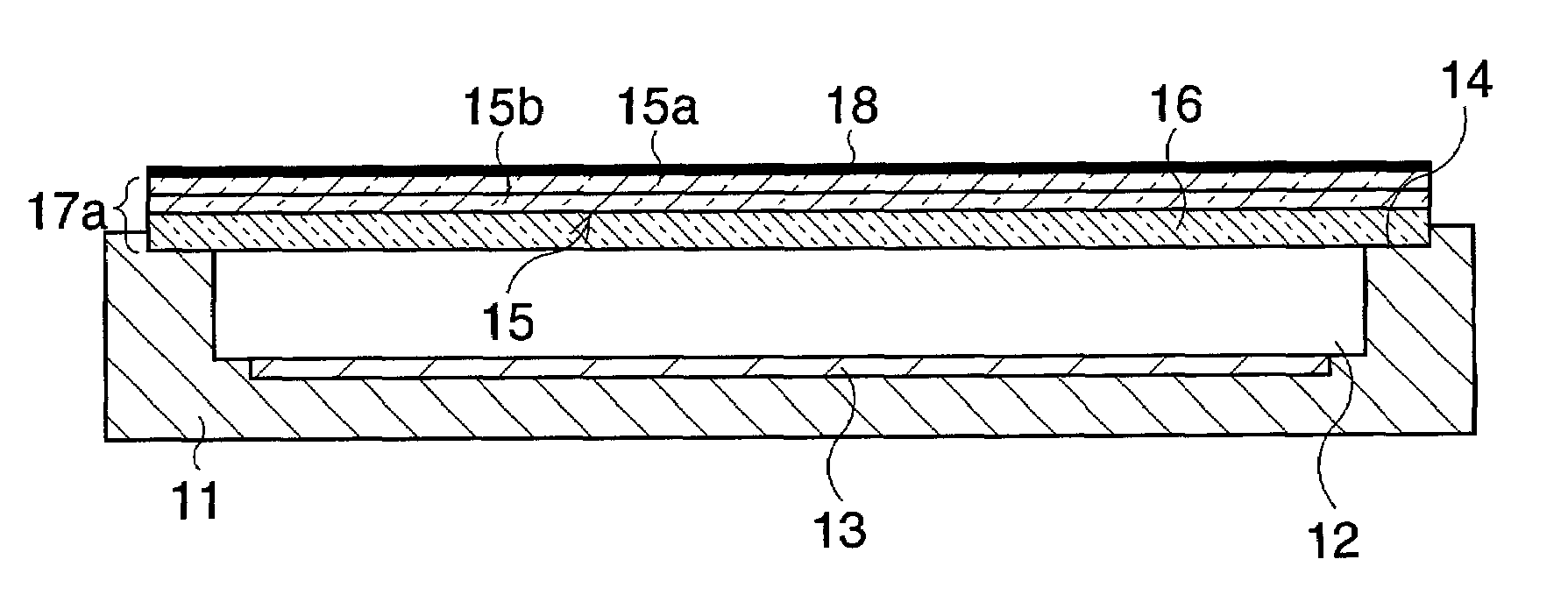
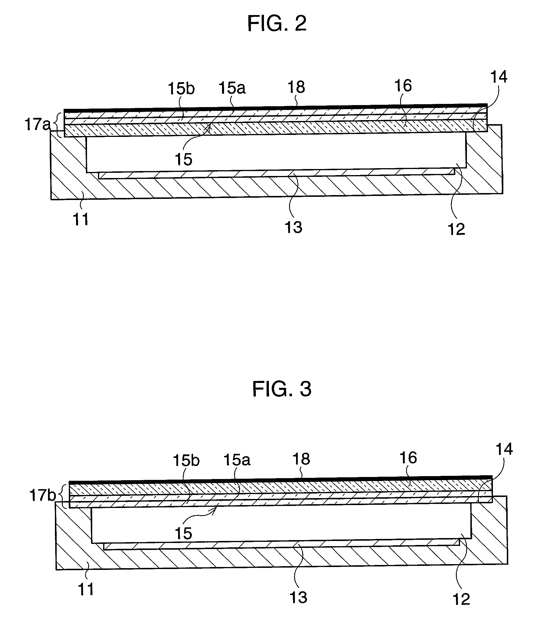
[0006]Therefore, an object of the present invention is to provide a transparent cover plate for a solid state imaging device which is able to prevent dust collecting on the surface of the cover plate. Further, an object of the present invention is to provide an image pickup device that utilizes the above transparent cover plate.

Problems solved by technology

However, the conventional structure for mounting the optical low-pass filter or infrared cut-off filter requires a comparatively large space between the taking lens and the image pickup device.
Accordingly, conventional structures limit design flexibility along the optical axis between the taking lens and the image pickup device.
However, when the optical low-pass filter or infrared cut-off filter is disposed closer to the image pickup device, an unfavorable effect to the quality of the taking images, caused by dust on the filters, increases.
Further, the conventional optical low-pass filter, infrared cut-off filter and cover glass are insulators, thus they attract dust in the air by electrostatic attraction.

Method used


Image

  • Image pickup device and cover plate with conductive film layer
  • Image pickup device and cover plate with conductive film layer
  • Image pickup device and cover plate with conductive film layer

Examples


example 1

[0031]Example 1 relates to a Cr conductive film. The deposit conditions for the Cr conductive film are shown in the table of FIG. 7. Namely, the deposition of the Cr conductive film was carried out under the following conditions: vacuum intensity at 2.0×10⁻⁵ torr, temperature of the LN plate at 100° C. and speed of the deposition at 20 nm / min. The thickness of the Cr conductive film was 1.7 nm. With above conditions, the film resistance between 1 cm distant electrodes was 870 kΩ. Surface potential of the LN plate before the Cr coating was about 0.5 kV and after the Cr coating was about 0.1 V. Hence the amount of surface potential of the LN plate was reduced by about three digits by the deposition of the Cr film. Note that, the surface potential was remotely measured by the DIGITAL STATIC METER MODEL 204 of Hugle Electronics Inc. To observe the effect of the Cr film coating, dust was sprinkled on a sample of the above Cr film coated LN plate, and a dust removal test was made with a b...

example 2

[0033]Example 2 relates to an Au conductive film. In example 2, the conductive film is deposited under the following conditions: vacuum intensity at 2.0×10⁻⁵ torr, temperature of the LN plate at 100° C. and speed of the deposition at 3.3 nm / min. The thickness of the Au conductive film was 3.3 nm. With the above conditions, the film resistance between 1 cm distant electrodes was above 40 MΩ. Surface potential of the LN plate before the Au coating was about 0.5 kV and after the Au coating was about 1.0 V. Namely, the surface potential of the LN plate was reduced about two digits by the deposition of the Au film coating. Further, in the same way as in example 1, to observe the effect of the Au film coating, dust was sprinkled on a sample of the Au film coated LN plate and a dust removal test was made with a blower. As a result, dust 10 μm in size or above was removed by the blower.

[0034]FIG. 9 is a graph of the transmissivity of the LN plate with the Au film, and the abscissa indicates...


PUM


Abstract

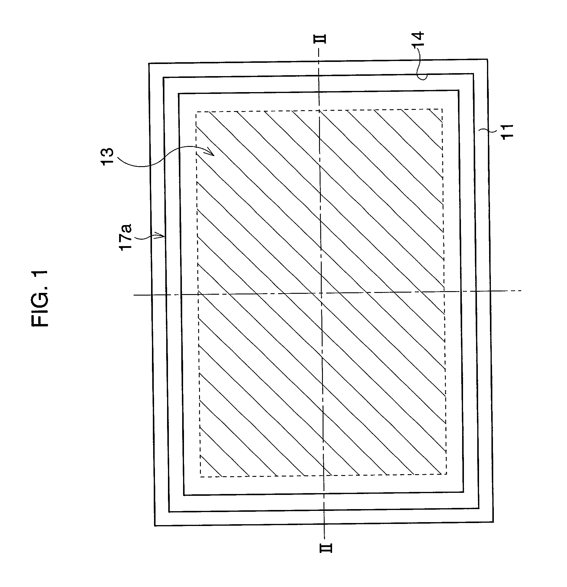
A cover plate for covering an opening of a casing in which a solid state imaging device is disposed. The cover plate comprises a transparent cover plate member and a conductive film layer. The cover plate hermetically covers the opening of the casing and the conductive film layer covers the outermost surface of the transparent cover plate member. The transparent cover plate member is comprised of a plurality of laminated transparent plates such as lithium niobate plates for an optical low-pass filter and a plate for an infrared cut-off filter. An example of the conductive film layer is a metallic film such as Cr or Au, coated on the surface.

Description

BACKGROUND OF THE INVENTION[0001]1. Field of the Invention[0002]The present invention relates to a transparent cover plate that shields a solid state imaging device of an image pickup device mounted in, for example, a digital still camera or digital video camera.[0003]2. Description of the Related Art[0004]Conventionally, in the art of digital still or video cameras, an optical low-pass filter or an infrared cut-off filter is interposed between a taking lens and an image pickup device to improve the quality of images taken by the cameras. The optical low-pass filter is used to suppress moiré fringes caused by beats or interference between a periodic pattern of an object and a pitch of pixels, in the image pickup device. The infrared cut-off filter prevents adverse effects of infrared rays to a captured image. However, the conventional structure for mounting the optical low-pass filter or infrared cut-off filter requires a comparatively large space between the taking lens and the ima...

Claims


Application Information

Patent Timeline
Patent Type & Authority Patents(United States)
IPC IPC(8): H04N5/225H01L27/14G02B5/20G02B27/46H01L23/02H01L31/02H04N25/00
CPCG02B5/208H04N5/2254H01L27/14618G02B27/46H01L2924/0002H01L27/14625H01L2924/00
Inventor FUSHIMI, MASAHIRONOMURA, YOSHIAKIMOGAMIYA, MAKOTO
Owner RICOH IMAGING COMPANY
Learn More