Zoom optical system

a technology of optical system and zoom, applied in the field of zoom optical system, can solve the problems of increasing the difficulty of providing good optical performance over the entire zoom range, increasing the difficulty of aberration correction, etc., and achieves good optical performance, comparatively bright imaging, and large aperture

Active Publication Date: 2006-05-23
FUJI PHOTO OPTICAL CO LTD
View PDF5 Cites 20 Cited by
  • Summary
  • Abstract
  • Description
  • Claims
  • Application Information

AI Technical Summary

Benefits of technology

[0008]The present invention relates to a compact zoom optical system that has good optical performance in both the visible light region and the near-infrared region, and provides comparatively bright imaging with a relatively large aperture, that is, with a small f-number, by using lens elements with aspheric surfaces that are produced according to current technical capabilities of manufacturing such lens elements.

Problems solved by technology

When an attempt to increase the brightness of the lens system is made, aberration correction becomes more difficult, and thus the difficulty of providing good optical performance over the entire zoom range also increases.
Due to recent progress in the technology of forming aspheric lenses, the conventional design limitation that lenses with aspheric surfaces should be formed with relatively small outer diameters and relatively small center thicknesses has become unnecessary, and even relatively large aspheric lenses can be formed.

Method used


Image

  • Zoom optical system
  • Zoom optical system
  • Zoom optical system

Examples


embodiment 1

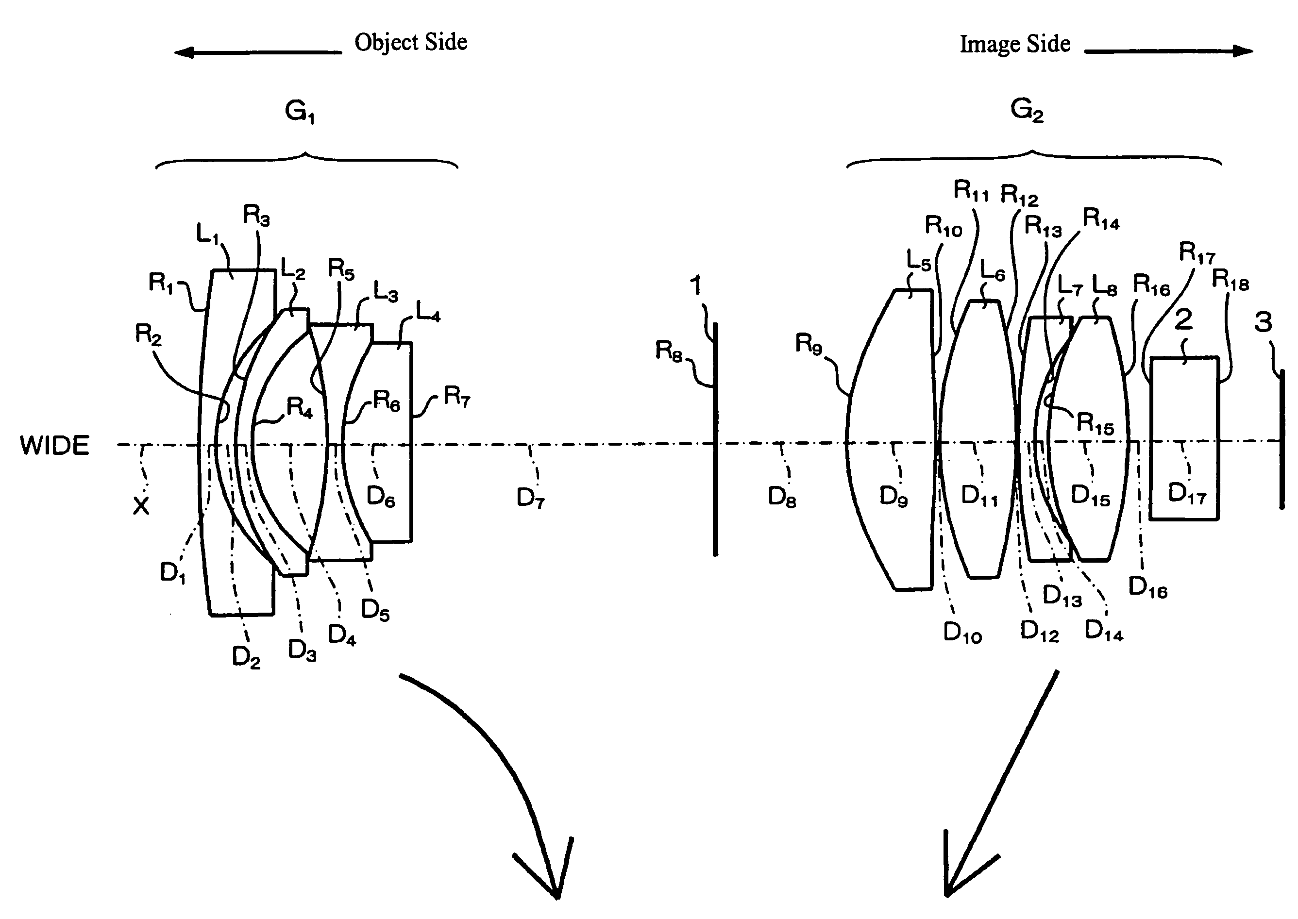
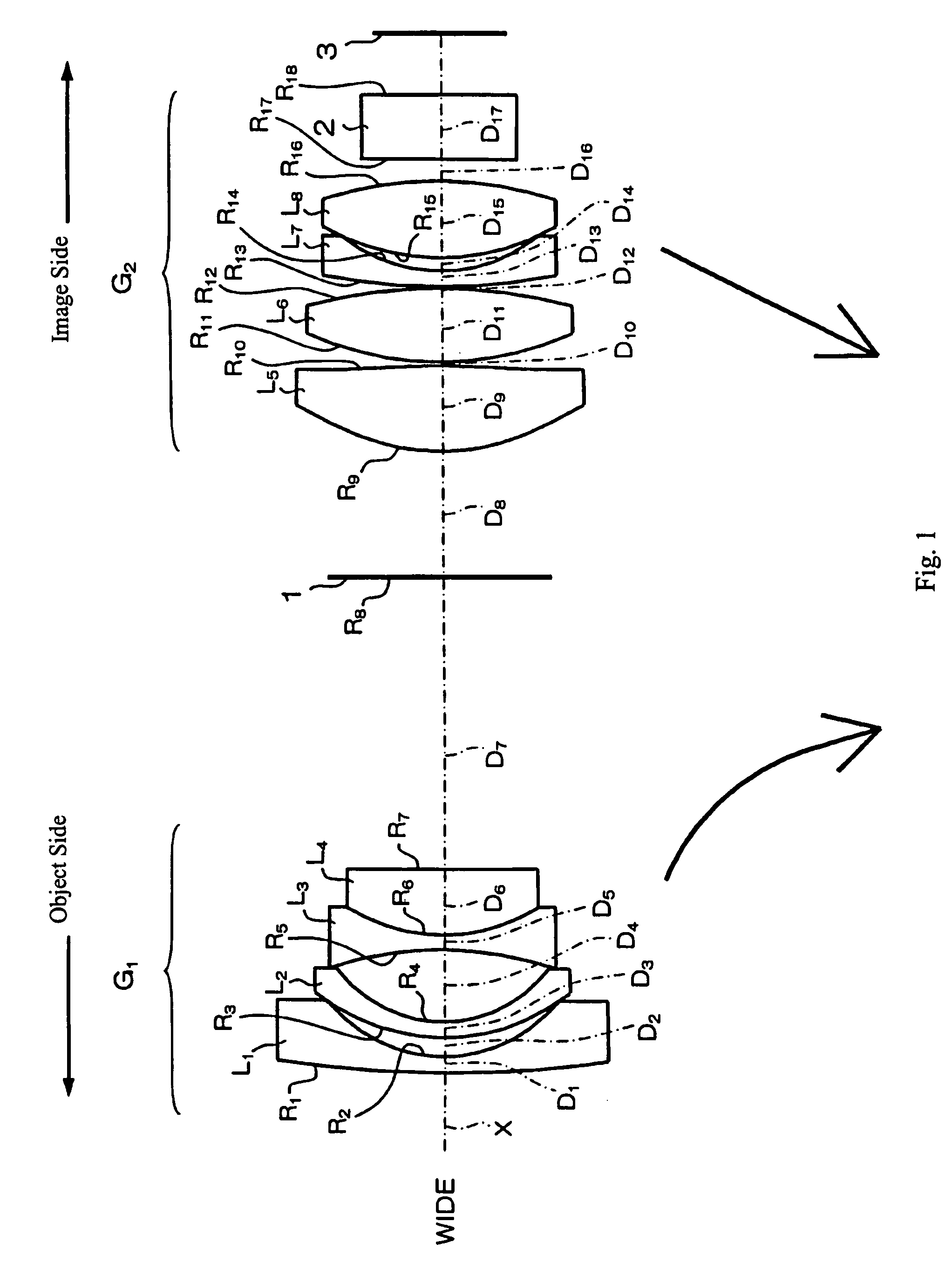
[0061]FIG. 1 shows a cross-sectional view of Embodiment 1 of the zoom optical system of the present invention at the wide-angle end.

[0062]Table 1 below lists the surface number #, in order from the object side, the radius of curvature R (in mm) of each surface on the optical axis, the on-axis surface spacing D (in mm), as well as the refractive index Nd and the Abbe number vd at the d-line (587.6 nm) of each optical element for Embodiment 1. Note that although R is the on-axis radius of curvature, for convenience of illustration, in FIG. 1 the lead lines from the R reference symbols extend to the surfaces being referenced but do not extend to the on-axis positions.

[0063]

TABLE 1#R.DNdνd 153.70910.781.8340037.2 27.07890.89 39.72060.701.5163364.1 46.28203.34 5−17.07700.701.6727032.1 68.59373.041.9228618.9 7∞D7 (variable) 8∞ (stop)D8 (variable) 9*10.18034.001.5891361.2 10*−34.34020.171115.16543.411.4970081.612−25.17420.101329.06230.701.9228618.9147.51440.631511.35233.511.7291654.716−17....

embodiment 2

[0073]FIG. 4 shows a cross-sectional view of Embodiment 2 of the zoom optical system of the present invention at the wide-angle end.

[0074]Table 5 below lists the surface number #, in order from the object side, the radius of curvature R (in mm) of each surface on the optical axis, the on-axis surface spacing D (in mm), as well as the refractive index Nd and the Abbe number vd at the d-line (587.6 nm) of each optical element for Embodiment 2. Note that although R is the on-axis radius of curvature, for convenience of illustration, in FIG. 4 the lead lines from the R reference symbols extend to the surfaces being referenced but do not extend to the on-axis positions.

[0075]

TABLE 5#RDNdνd 133.51250.781.8340037.2 26.39191.91 314.52810.701.5163364.1 46.43833.10 5−14.61560.701.6727032.1 68.66153.051.9228618.9 7−109.7845D7 (variable) 8∞ (stop)D8 (variable) 9*10.22284.001.5891361.2 10*−33.97550.341113.68153.381.4970081.612−25.09590.121330.78710.701.9228618.9147.17040.591510.66623.391.7291654...


PUM


Abstract

A comparatively low f-number, compact two-group zoom optical system that corrects aberrations in the visible and the near-infrared regions includes, in order from the object side, a first lens group of negative refractive power and a second lens group of positive refractive power. The first lens group includes three lens components that are lens elements of negative, negative, negative, and positive refractive power, respectively, in order from the object side. The second lens group includes four lens components that are lens elements of positive, positive, negative, and positive refractive power, respectively, in order from the object side. Aspheric surfaces are disclosed. Certain conditions relating to the focal lengths of the two lens groups, indexes of refraction and Abbe numbers of various lens elements, and radii of curvature of an interior lens element of the second lens group are satisfied to control aberrations in both the visible and the near-infrared regions.

Description

TECHNICAL FIELD OF THE INVENTION[0001]The present invention relates to a zoom optical system that can be used in various kinds of video cameras and electronic still cameras that include CCDs (Charge Coupled Devices) as image detectors, and relates especially to a zoom optical system that operates with both visible light in the 400–700 nm range and near-infrared light in the 700–1000 nm range, which are preferable ranges for monitoring camera lenses.BACKGROUND OF THE INVENTION[0002]While the demand for monitoring cameras has been increasing in order to operate unmanned monitoring facilities, there has also been a demand in recent years for zoom lenses that operate both in the visible light region for operating with visible light during the day and in the near-infrared region for operating with near-infrared light at night. An example of such a zoom optical system including a zoom lens is described in Japanese Laid-Open Patent Application 2002-196235.[0003]The zoom lens described in J...

Claims


Application Information

Patent Timeline
Patent Type & Authority Patents(United States)
IPC IPC(8): G02B15/14
CPCG02B15/177
Inventor TOMIOKA, UKYO
Owner FUJI PHOTO OPTICAL CO LTD
Why Eureka
Try Eureka