Method of detecting path timings and CDMA receiving apparatus using the same

a technology of detecting path timing and receiving apparatus, which is applied in the direction of electrical apparatus, radio transmission, diversity/multi-antenna systems, etc., can solve the problems of deteriorating reception characteristic and reception characteristic, and achieve error-free, strong path, good reception characteristic

Inactive Publication Date: 2006-05-23
NEC CORP
View PDF16 Cites 9 Cited by
  • Summary
  • Abstract
  • Description
  • Claims
  • Application Information

AI Technical Summary

Benefits of technology

[0023]Therefore, an object of the present invention is to provide a CDMA receiving apparatus and a method of detecting path timings in which the optimal threshold value processing can be carried out even in all the p...

Problems solved by technology

However, there are the following problems in the above-mentioned conventional technique. FIG. 3 is a graph showing a conventional threshold value processing example in the propagation environment in which there is a stronger path so as to be error fee.
The first problem is in that a path unstable near a noise level is used for the RAKE synthesis depending on the value of the maximum peak level threshold value in the propagation environment in which there is so a stronger path as to be error f...

Method used


Image

  • Method of detecting path timings and CDMA receiving apparatus using the same
  • Method of detecting path timings and CDMA receiving apparatus using the same
  • Method of detecting path timings and CDMA receiving apparatus using the same

Examples


first embodiment

The First Embodiment

[0054]The CDMA receiving apparatus and the method of detecting path timings of the first embodiment of the present invention will be described with reference to FIGS. 5 to 10C and a table 1. First, the structure and operation in the first embodiment will be described with reference to FIGS. 5 to 7.

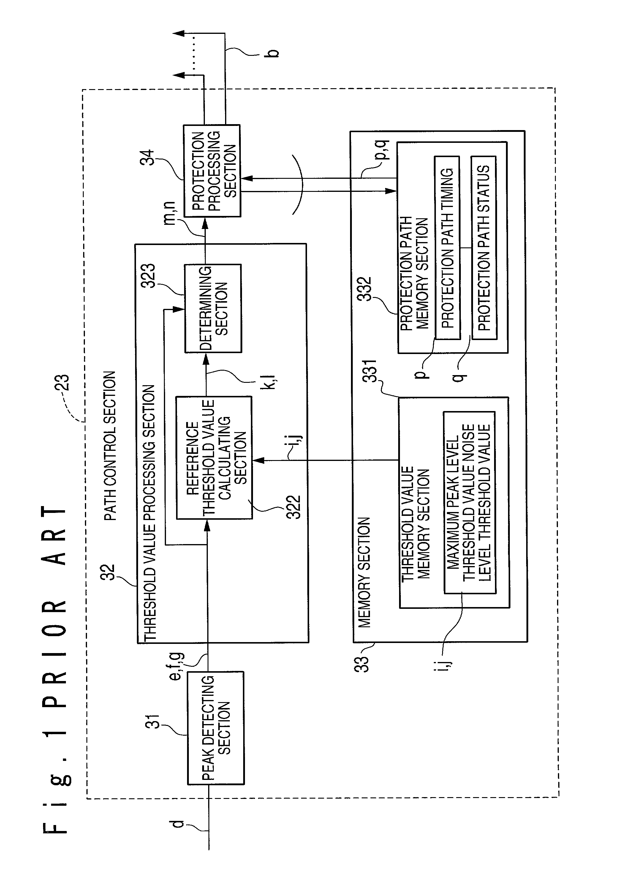
[0055]FIG. 5 is a block diagram showing the structure of the CDMA receiving apparatus in the first embodiment.

[0056]As shown in FIG. 5, the CDMA receiving apparatus 10 is composed of a finger section 11, a searcher section 12, a RAKE synthesizing section 13 and a decoding section 14. Also, the above-mentioned finger section 11 is composed of n finger units.

[0057]A reception signal inputted to the CDMA receiving apparatus 10 is supplied to the finger section 11 and the searcher section 12, respectively. The searcher section 12 finds correlation values while shifting the timing of the despreading of the reception signal a little by little, and looks for the optimal recept...

second embodiment

The Second Embodiment

[0082]Next, the CDMA receiving apparatus and the method of detecting path timings according to the second embodiment of the present invention will be described with reference to FIG. 11.

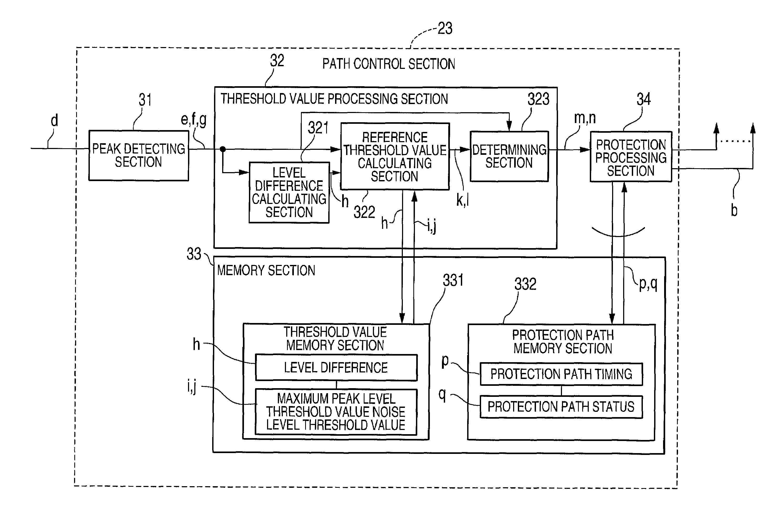
[0083]FIG. 11 is a block diagram showing the detailed structure of the path control section 23 of the second embodiment. As shown in FIG. 11, the path control section 23 in the second embodiment is composed of the components like those of the above-mentioned first embodiment. However, the second embodiment is different from the above-mentioned first embodiment in the point that the path control section 23 in the second embodiment is connected to the protection path memory section 332 and the level calculating section 321.

[0084]The operation of the second embodiment in which the protection path memory section 332 is connected with the level difference calculating section 321 will be described.

[0085]In case of path detection, the level is easy to change in a moment due to fading an...

third embodiment

The Third Embodiment

[0091]Next, the CDMA receiving apparatus and the method of detecting path timings according to the third embodiment of the present invention will be described with reference to FIG. 12. FIG. 12 is a block diagram showing the detailed structure of the path control section 23 of the third embodiment. As shown in FIG. 12, the path control section 23 in the third embodiment is composed of the components like those of the above-mentioned first embodiment and a time average memory section 333 is provided as a new component in the memory section 33. In the current cycle average memory section 333 are stored a noise level time average v and a valid path level time average x. Also, the third embodiment is different from the first embodiment in that the above protection path memory section 332 and the above-mentioned level calculating section 321 are connected but is same as the above-mentioned second embodiment. Moreover, the third embodiment differs from the above-mentio...


PUM


Abstract

A CDMA receiving apparatus includes a searcher section, a finger section, a RAKE synthesizing section and a decoding section. The searcher section has a protection path memory, generates a delay profile from a reception signal, and finds peaks from the delay profile based on a variable peak level reference threshold value and a variable noise level reference threshold value which are determined based on the delay profile. Also, the searcher section reads out protection path data in a previous cycle from the protection path memory, and determines timings of valid paths based on timing of the found peaks and protection path timings of the read out protection path data. The finger section detects a signal from the reception signal for every path in response to the valid path timings. The RAKE synthesizing section carries out RAKE synthesis to the detected signals to produce a RAKE synthesis signal. The decoding section decodes the RAKE synthesis signal.

Description

BACKGROUND OF THE INVENTION[0001]1. Field of the Invention[0002]The present invention relates to a CDMA (Code division multiple access) receiving apparatus and a method of detecting a path.[0003]2. Description of the Related Art[0004]A CDMA receiving apparatus is conventionally known which is composed of a finger section, a searcher section and a RAKE synthesizing section, the searcher section is composed of a correlation unit group, an adder group and a path control section. The path control section searches a reception timing with a high level from correlation values before and after the addition, and the finger section determines the reception timing. The finger section detects a valid path at the determined reception timing, and the RAKE synthesizing section RAKE-synthesizes the detected paths.[0005]The path control section in the conventional CDMA receiving apparatus will be described below with reference to FIG. 1.[0006]FIG. 1 is a block diagram showing the structure of the pa...

Claims


Application Information

Patent Timeline
IPC IPC(8): H04B1/707H04B1/7115H04B7/02
CPCH04B1/70755H04B1/7115
Inventor HIRADE, SEI
Owner NEC CORP
Why Eureka
Try Eureka