
Performance throttling for temperature reduction in a microprocessor

Inactive Publication Date: 2006-05-23
IBM CORP
View PDF5 Cites 69 Cited by
  • Summary
  • Abstract
  • Description
  • Claims
  • Application Information

AI Technical Summary

Benefits of technology

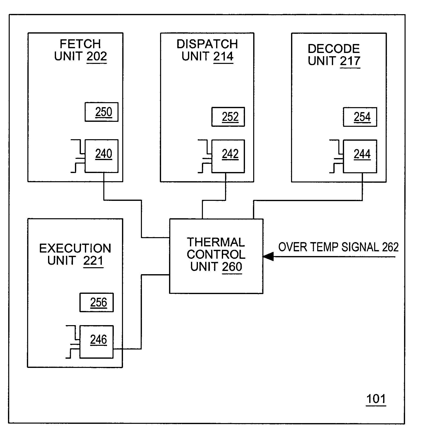
[0005]The identified goal is achieved by a microprocessor having a functional block that includes dynamic power savings circuitry, a functional block control unit, and a thermal control unit. The functional block control units are capable of altering performance characteristics of their associated functional blocks automatically upon detecting an over temperature condition. The thermal control unit receives an over-temperature signal indicating a processor temperature condition exceeding a threshold and invokes one or more of the functional block control units in response to the signal. The functional block control units respond to signals from the thermal control unit by reducing processor activity, slowing processor performance, or a combination thereof. The reduced activity that results causes the dynamic power saving circuitry to engage. The functional block control units can throttle performance by numerous means including reducing the exploitable parallelism within the processor, suspending out-of-order execution, reducing effective resource size, and the like.

Problems solved by technology

As microprocessor designs grow increasingly more complex, they demand a larger functional area and typically consume more power.
In modem microprocessors, dense packing of heat producing functional blocks and very high clock speeds can cause the generation of more heat than the device is physically capable of dissipating.
Unfortunately, it is not always possible to address this problem by simply consuming more space or eliminating selected functional blocks.

Method used


Image

  • Performance throttling for temperature reduction in a microprocessor
  • Performance throttling for temperature reduction in a microprocessor
  • Performance throttling for temperature reduction in a microprocessor

Examples


Embodiment Construction

[0011]Generally speaking, the present invention encompasses a microprocessor employing a self-regulating thermal control mechanism. More specifically, the microprocessor includes power saving circuits that engage during periods of reduced processor activity. The processor also includes a thermal control unit that causes the power saving circuits to engage when the processor temperature exceeds some threshold value. The power saving circuits, when engaged, reduce the performance characteristics of the processor to reduce the amount of thermal energy produced by the processor thereby reducing the processor's temperature. When the temperature drops back below a lower threshold, the performance limiting corrections taken to reduce the chip's temperature may be de-activated to restore full functionality and maximum performance to the processor.

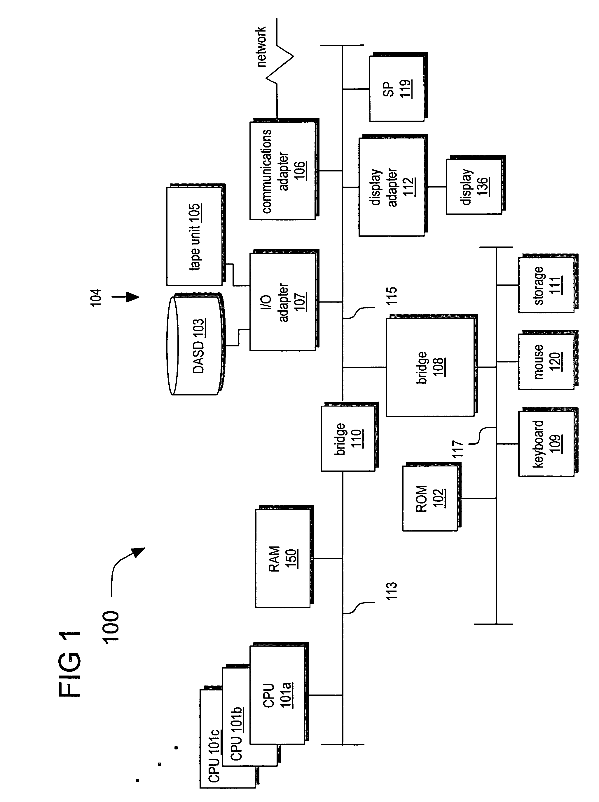
[0012]Referring now to FIG. 1, an embodiment of a data processing system 100 according to the present invention is depicted. System 100 includes o...


PUM


Abstract

A microprocessor includes a functional block having dynamic power savings circuitry, a functional block control circuit, and a thermal control unit. The functional block control circuits are capable of altering performance characteristics of their associated functional blocks automatically upon detecting an over temperature condition. The thermal control unit receives an over-temperature signal indicating a processor temperature exceeding a threshold and invokes the one or more of the functional block control units in response to the signal. The functional block control units respond to signals from the thermal control unit by reducing processor activity, slowing processor performance, or both. The reduced activity that results causes the dynamic power saving circuitry to engage. The functional block control units can throttle performance by numerous means including reducing the exploitable parallelism within the processor, suspending out-of-order execution, reducing effective resource size, and the like.

Description

BACKGROUND[0001]1. Field of the Present Invention[0002]The present invention generally relates to the field of microprocessors and more particularly to methods of controlling the amount of heat dissipated by a microprocessor.[0003]2. History of Related Art[0004]As microprocessor designs grow increasingly more complex, they demand a larger functional area and typically consume more power. The area required to implement the necessary features of modem microprocessors has caused the industry to concentrate on moving devices increasingly closer together to limit physical chip sizes and increase clock speed. Because of this trend, power density has become a major consideration in the design of microprocessors. In modem microprocessors, dense packing of heat producing functional blocks and very high clock speeds can cause the generation of more heat than the device is physically capable of dissipating. Unfortunately, it is not always possible to address this problem by simply consuming mo...

Claims


Application Information

Patent Timeline
IPC IPC(8): G06F1/32G06F1/20
CPCG06F1/206G06F1/324G06F1/3287G06F9/30149G06F9/3017G06F9/3802G06F9/3851G06F9/3853G06F9/3867G06F9/3885G06F1/3203Y02B60/32Y02B60/1217Y02B60/1275Y02B60/1282Y02D10/00Y02D30/50
Inventor CLABES, JOACHIM GERHARDFLOYD, MICHAEL STEPHENKALLA, RONALD NICKSINHAROY, BALARAM
Owner IBM CORP
Learn More