Respirator mask

a technology for respirator helmets and masks, applied in the field of respirator helmets, can solve the problems of patents that are not dustproof enough, and the helmet is disclosed, and achieve the effect of reducing the accumulation of particulates

Inactive Publication Date: 2006-05-30
SCOTT TECH INC
View PDF6 Cites 19 Cited by
  • Summary
  • Abstract
  • Description
  • Claims
  • Application Information

AI Technical Summary

Benefits of technology

[0008]The present invention is directed to a respiratory helmet. The helmet is designed to provide protection to a user's cranium area. The helmet also has a visor designed to provide protection to the user's face area, an air intake system, and a parallel elliptical rail system. The visor can be positioned on the helmet, in front of the user's face area, and any position in between. The area between the visor, when the visor is positioned in front of the user's face area and the face area is called the breathing zone. The visor has at least two wheels, a top side and a bottom side wherein the bottom side is positioned closer to the user's chin when the visor is positioned in front of the user's face. The air intake system has an intake unit that receives a gaseous medium from a gaseous medium supply system or the ambient air into the helmet, and the intake unit directs the gaseous medium toward the breathing zone. The parallel elliptical rail system allows the visor to move in an elliptical motion. Each rail receives at least one wheel of the visor, and is designed to decrease the accumulation of particulates on the rail.

Problems solved by technology

The helmet disclosed in the '929 patent, however, was apparently not sufficiently dust proof because Racal filed another application that matured into the '688 patent that addressed that problem.

Method used


Image

  • Respirator mask
  • Respirator mask
  • Respirator mask

Examples


Embodiment Construction

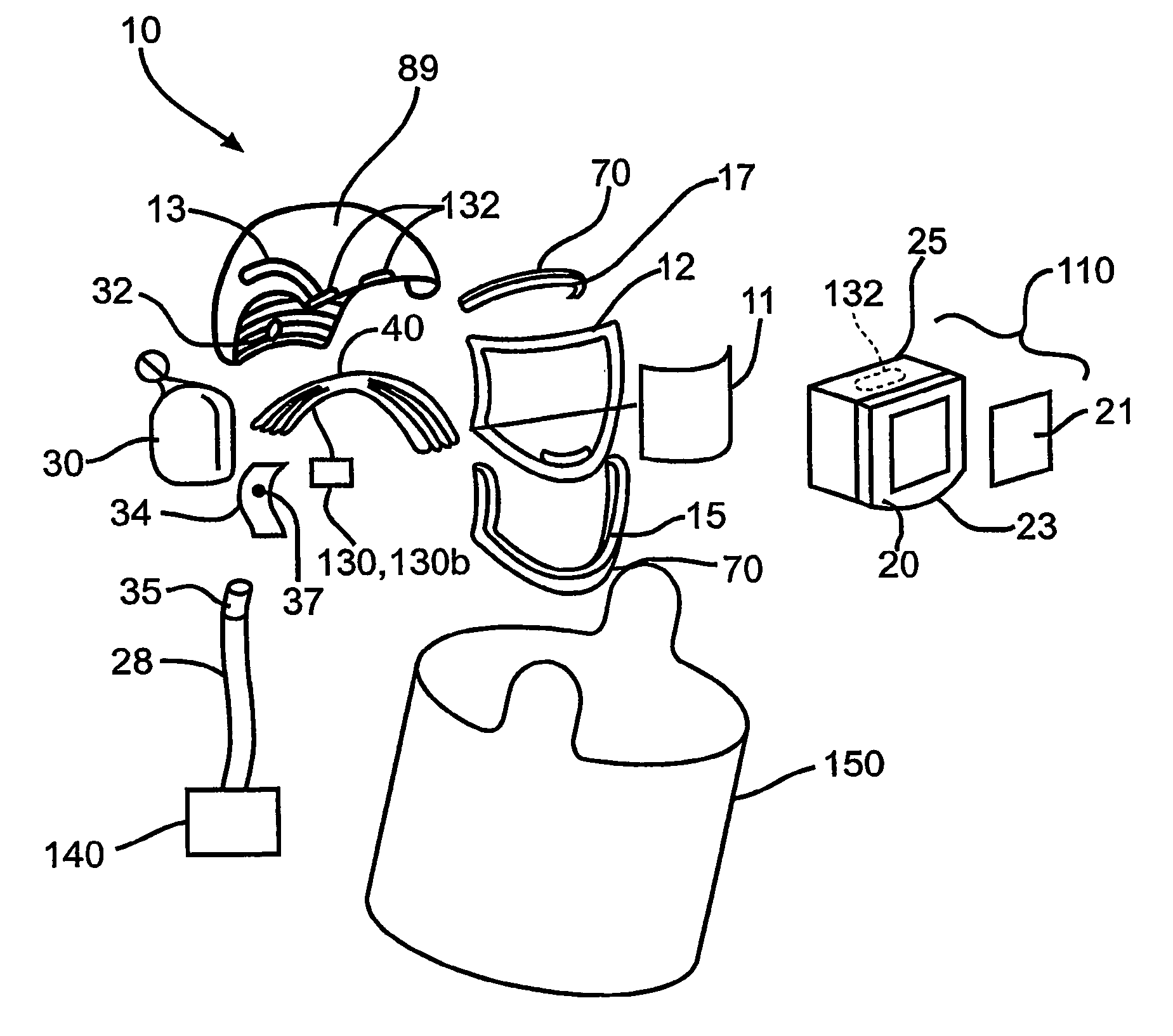
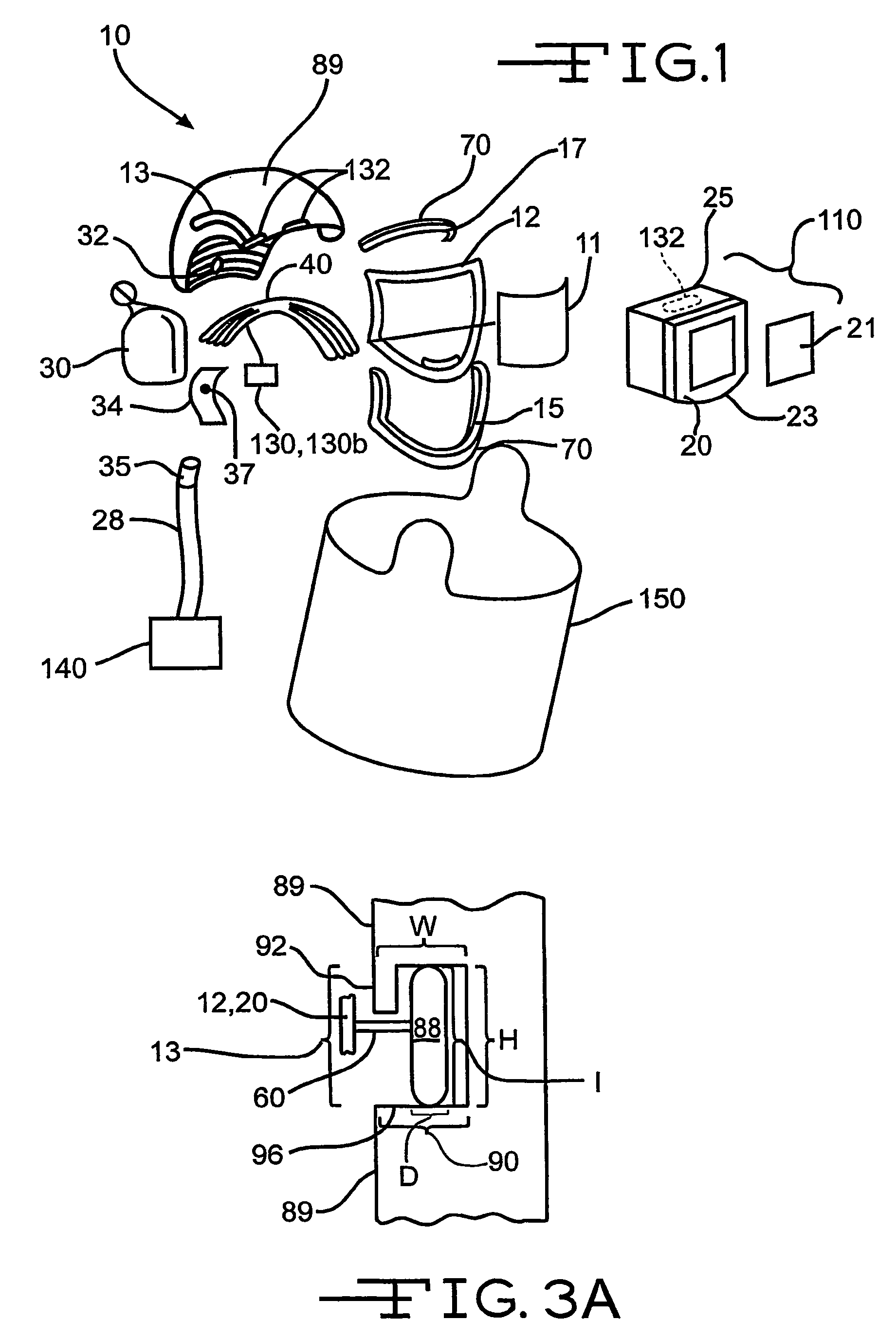
[0017]FIG. 1 shows an exploded view of respirator helmet 10 including a first visor assembly 11, a second visor assembly 110. The first visor assembly 11 includes a frame member 12 which is attached by way of wheels, preferably made of elastomeric plastic material and will be identified as item 88, to parallel elliptical rails 13 on the exterior surface 89 of the helmet 10. Each rail 13 has a profile designed to (1) avoid the accumulation of dirt on the rails and on the wheels, (2) make the wheels have a narrow contact on the rails 13.

[0018]Turning to FIGS. 3a, 3b, and 3c, these figures illustrate cross-sectional views of a wheel 88 within a portion of the rail 13. The rail 13 is a part of the exterior surface of the helmet 10. The rail 13 has a recess area 90 that intrudes into the helmet 10. The recess area 90 has a width W and height H which are respectively greater than, or in at least one embodiment equal to, the width D and height I of the wheel 88 which allows the wheels 88 t...


PUM


Abstract

The present invention is directed to a respiratory helmet. The helmet is designed to provide protection to a user's cranium area. The helmet also has a visor designed to provide protection to the user's face area, an air intake system, and a parallel elliptical rail system. The visor can be positioned on the helmet, in front of the user's face area, and any position in between. The area between the visor, when the visor is positioned in front of the user's face area and the face area is called the breathing zone. The visor has at least two wheels, a top side and a bottom side wherein the bottom side is positioned closer to the user's chin when the visor is positioned in front of the user's face. The air intake system has an intake unit that receives a gaseous medium from a gaseous medium supply system or the ambient air into the helmet, and the intake unit directs the gaseous medium toward the breathing zone. The parallel elliptical rail system allows the visor to move in an elliptical motion. Each rail receives at least one wheel of the visor, and is designed to decrease the accumulation of particulates on the rail.

Description

CLAIM OF PRIORITY[0001]This application claims priority to U.S. provisional application Ser. No. 60 / 285,876 that was filed on Apr. 23, 2001.FIELD OF THE INVENTION[0002]The present invention is directed to a respirator helmet with a movable visor.BACKGROUND OF THE INVENTION[0003]There are numerous types of respirator helmets. Many respirator helmets have an interior space between the head and the interior surface of the respirator helmet. Within that space, the respirator helmet is designed to forward a sufficient amount of air toward the nose and mouth of the user of the respirator helmet. The air is forwarded toward the user's breathing orifices by either a built-in air filter and fan, or by a remote air supply system that feeds the air into the helmet interior through a suitable tube or pipe. Containing the air about the user's orifices is accomplished through a suitable design of a full-face visor, normally transparent. Examples of these respiratory helmets are disclosed in U.S. ...

Claims


Application Information

Patent Timeline
Patent Type & Authority Patents(United States)
IPC IPC(8): A62B7/10A42B3/04A42B3/22A42B3/32A61F9/06A62B7/12A62B18/04
CPCA42B3/0433A42B3/22A62B18/04A42B3/326A42B3/288A62B18/02
Inventor UUSITALO, JUSSI SEVERIJARVINEN, JYRKI HANNU VELIKINNUNEN, JUHA ANTERONENONEN, VILLE-PETTERI
Owner SCOTT TECH INC
Why Eureka
Try Eureka