
Viscous liquid dispenser having leak prevention device

a liquid dispenser and valve technology, applied in liquid handling, instruments, applications, etc., can solve the problems of improper seating of check valves, failure of locking mechanisms to fully stop leakage, etc., to facilitate sealing engagement of the cap, prevent leakage, and facilitate the releasable attachment of the radial extension member to the check valve mechanism

Inactive Publication Date: 2006-05-30
KIMBERLY-CLARK WORLDWIDE INC
View PDF32 Cites 3 Cited by
  • Summary
  • Abstract
  • Description
  • Claims
  • Application Information

AI Technical Summary

Benefits of technology

Effectively prevents leaks during shipment and storage by engaging the check valve mechanism and sealing the dispensing channel, ensuring the dispenser remains leak-proof even when the locking mechanism allows slight movement.

Problems solved by technology

However, locking mechanisms often fail to fully stop leakage, especially in those pumps having a pump mechanism at or below the level of the liquid in the dispenser.
Also, check valves may improperly seat and allow small leaks that would be insignificant during dispensing, but become significant during extended periods of shipment or storage.

Method used


Image

  • Viscous liquid dispenser having leak prevention device
  • Viscous liquid dispenser having leak prevention device
  • Viscous liquid dispenser having leak prevention device

Examples


Embodiment Construction

[0025]Reference will now be made in detail to embodiments of the invention, one or more examples of which are provided in the drawings. Each example is provided by way of explanation of the invention and not meant as a limitation of the invention. For example, features illustrated or described as part of one embodiment may be utilized with another embodiment to yield still a further embodiment. It is intended that the present invention include such modifications and variations as come within the scope of the appended claims and their equivalents.

[0026]The present invention relates to a unique dosing pump having a leak protection device for use with any manner of liquid dispenser. The pump apparatus is particularly well suited for use with any manner of viscous liquid dispenser, for example soap dispensers, lotion dispenser, and the like. The present invention also encompasses a dispenser utilizing the unique pump according to the invention. Examples of dispensers that may benefit fr...


PUM


Abstract

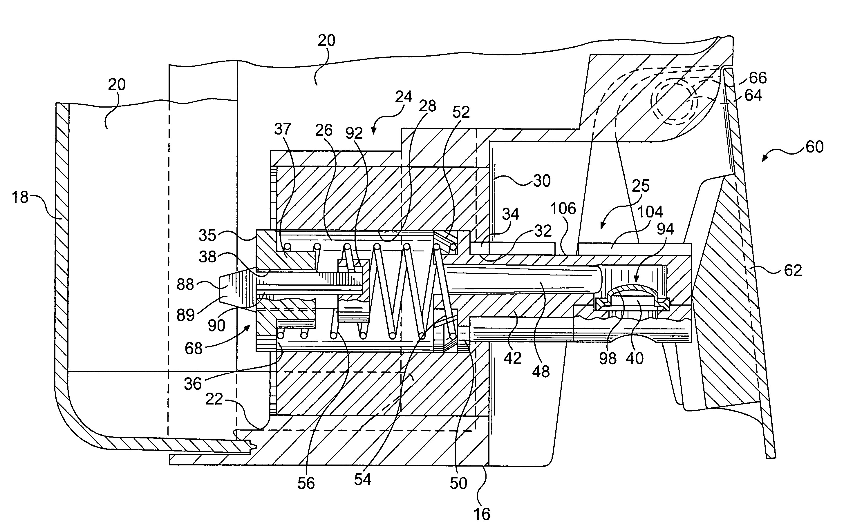
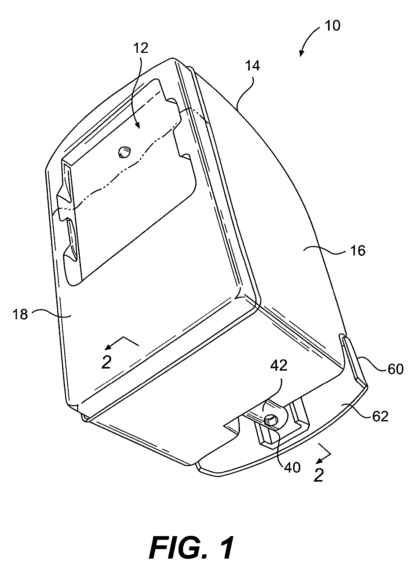
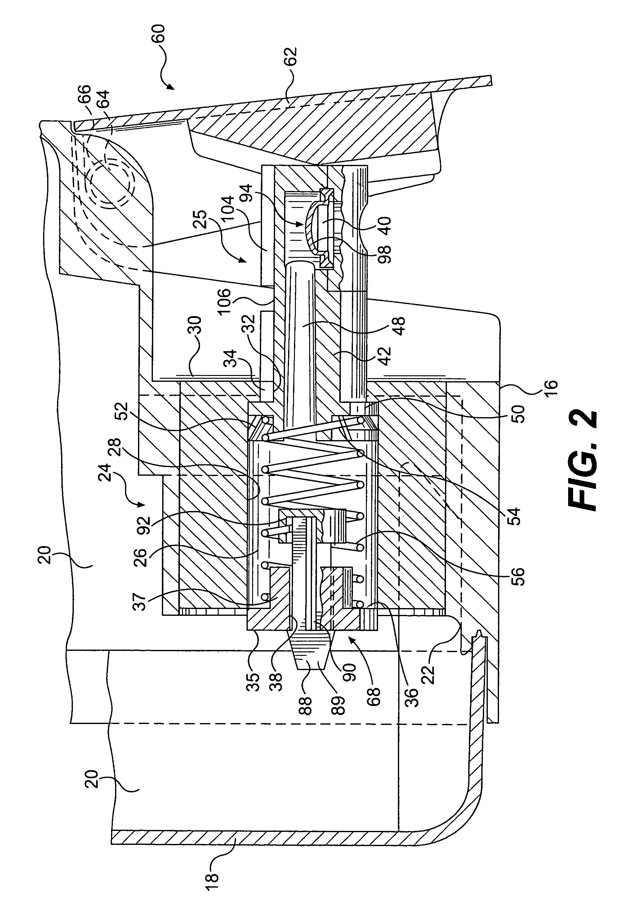
A dispenser for dispensing metered amounts of a viscous liquid includes a liquid reservoir and a pump chamber having an opening in communication with the reservoir. A pump mechanism including a pump cylinder with a dispensing channel therethrough is configured with the pump chamber and is movable from a rest to a pressurizing position upon actuation thereof to pressurize liquid within the pump chamber. A dispensing orifice is defined at one end of the dispensing cylinder. A check valve mechanism is disposed in the opening. During shipment or storage, the pump cylinder is locked in pressurized position. When locked in pressurized position, the dispensing channel engages the check valve to seal the opening and also prevent flow from the pump chamber to the dispensing channel.

Description

BACKGROUND OF THE INVENTION[0001]Viscous liquid dispensers are well known in the art for dispensing any manner of viscous liquid, for example lotions, soap, and the like. The conventional dispensers utilize a wide variety of pumping mechanisms which allow a user to depress or manipulate a pump actuator in order to dispense liquid from the dispenser. Exemplary devices are shown, for example, in U.S. Pat. Nos. 5,810,203; 5,379,919; 5,184,760; and 4,174,056.[0002]Conventional dispensers and pump mechanisms are often configured with locking mechanisms to reduce leakage during shipment or storage. However, locking mechanisms often fail to fully stop leakage, especially in those pumps having a pump mechanism at or below the level of the liquid in the dispenser.[0003]Pump mechanisms with check valves are also known. However, check valves are often designed to work in conjunction with pressure developed through activation of the pump. When the pump is in locked position, there is no pressur...

Claims


Application Information

Patent Timeline
Patent Type & Authority Patents(United States)
IPC IPC(8): B67B1/08A47K5/12
CPCA47K5/1204
Inventor LEWIS, RICHARD PAULBACHTEL, RANDALL MARC
Owner KIMBERLY-CLARK WORLDWIDE INC
Learn More