
Illumination device

a technology of a slit-type device and a slit-type body, which is applied in the direction of mechanical equipment, lighting and heating equipment, instruments, etc., can solve the problems of new challenges and achieve the effect of improving spatial or spectral uniformity

Inactive Publication Date: 2006-05-30
3M INNOVATIVE PROPERTIES CO
View PDF10 Cites 123 Cited by
  • Summary
  • Abstract
  • Description
  • Claims
  • Application Information

AI Technical Summary

Benefits of technology

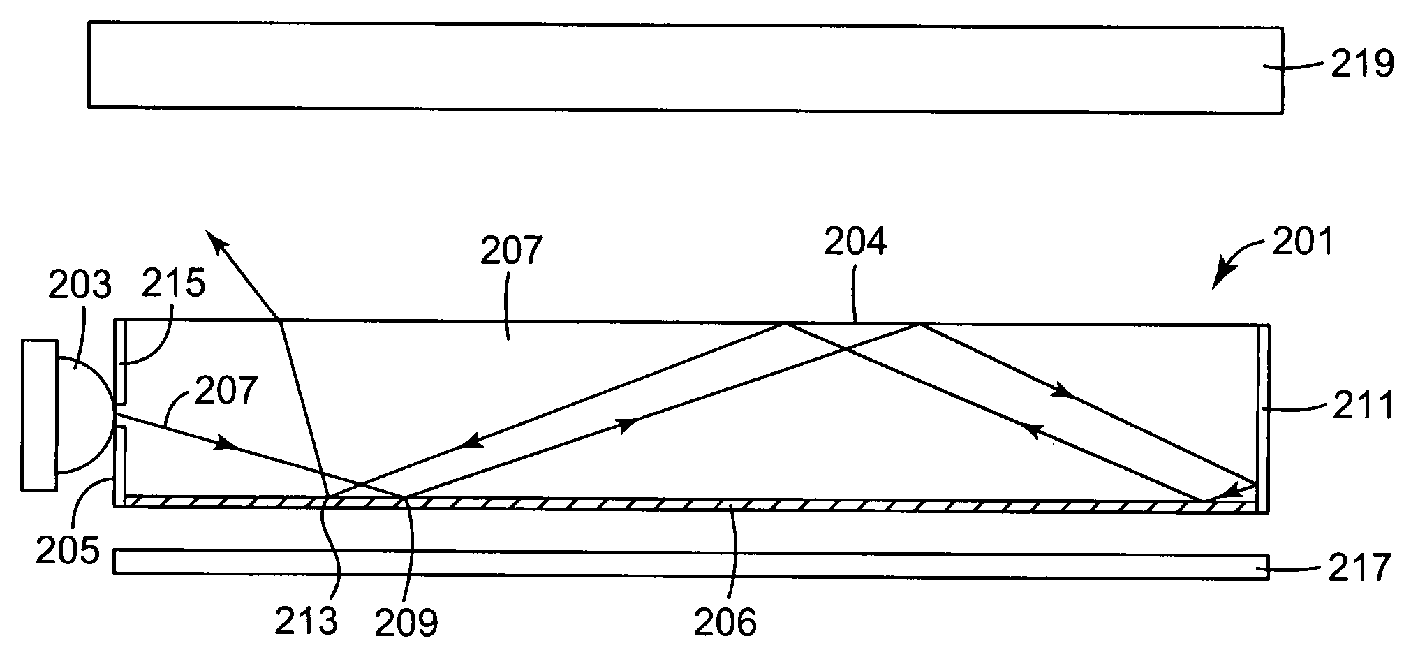
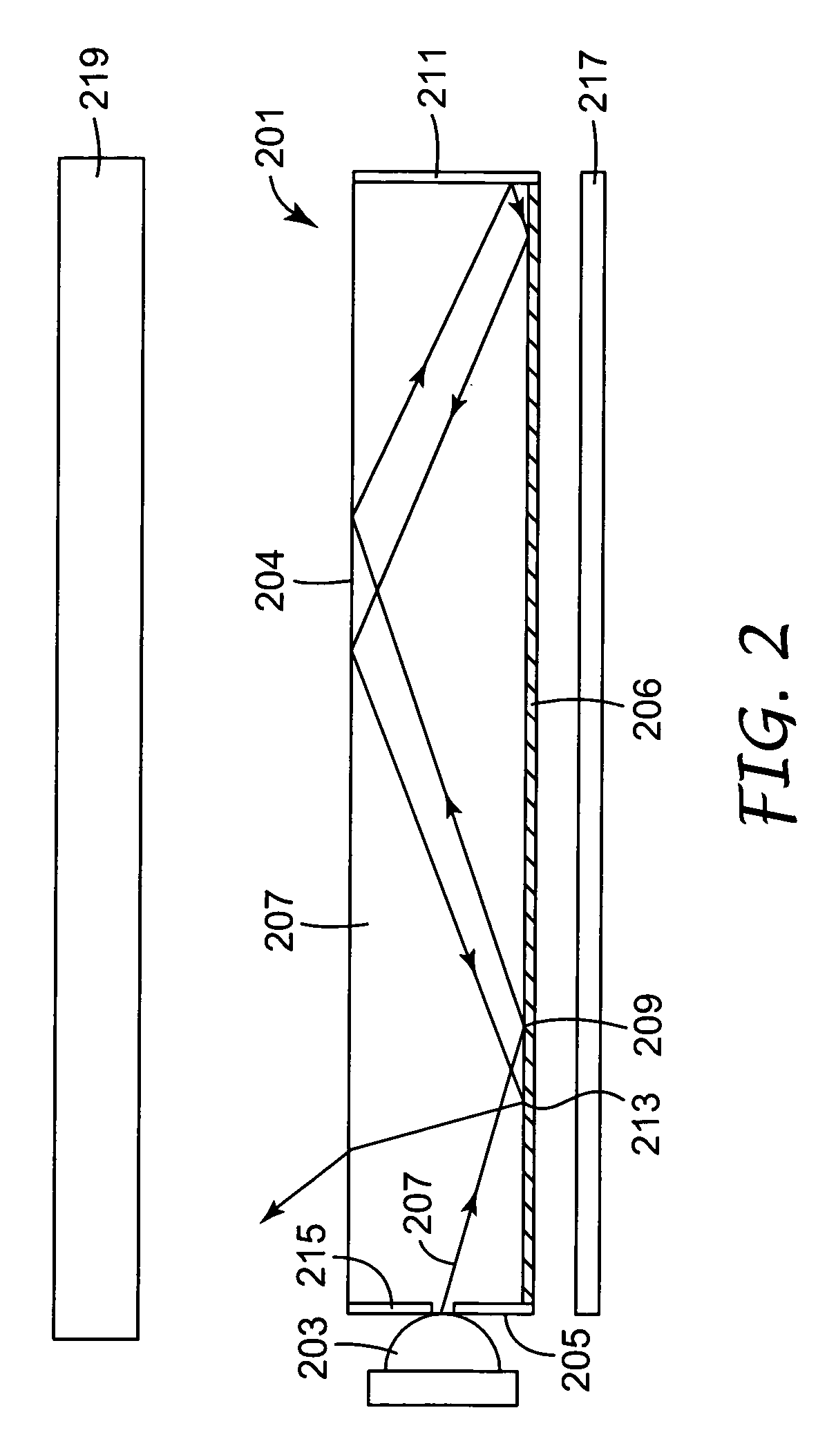
The present invention relates to improved illumination systems. One embodiment includes a light guide with extraction structures that extract more light from the guide when the light is propagating in a direction toward the light input area than when it is propagating in a direction away from the light input area. This allows the light to remain in the guide for a sufficient amount of time to improve spatial or spectral uniformity. The light guide can be combined with means for redirecting light extracted from the guide in a preferred direction. The invention also includes the use of different colored LEDs to generate light, which can be distributed over the surface of the light guide using extraction structures that extract both the different colored LEDs and provide spatial uniformity for the extracted light. The invention also includes the use of solid and hollow light guides, as well as additional structures to control the angular direction of light extracted from the guide. The illumination system can be used to illuminate a display panel, such as an LCD.

Problems solved by technology

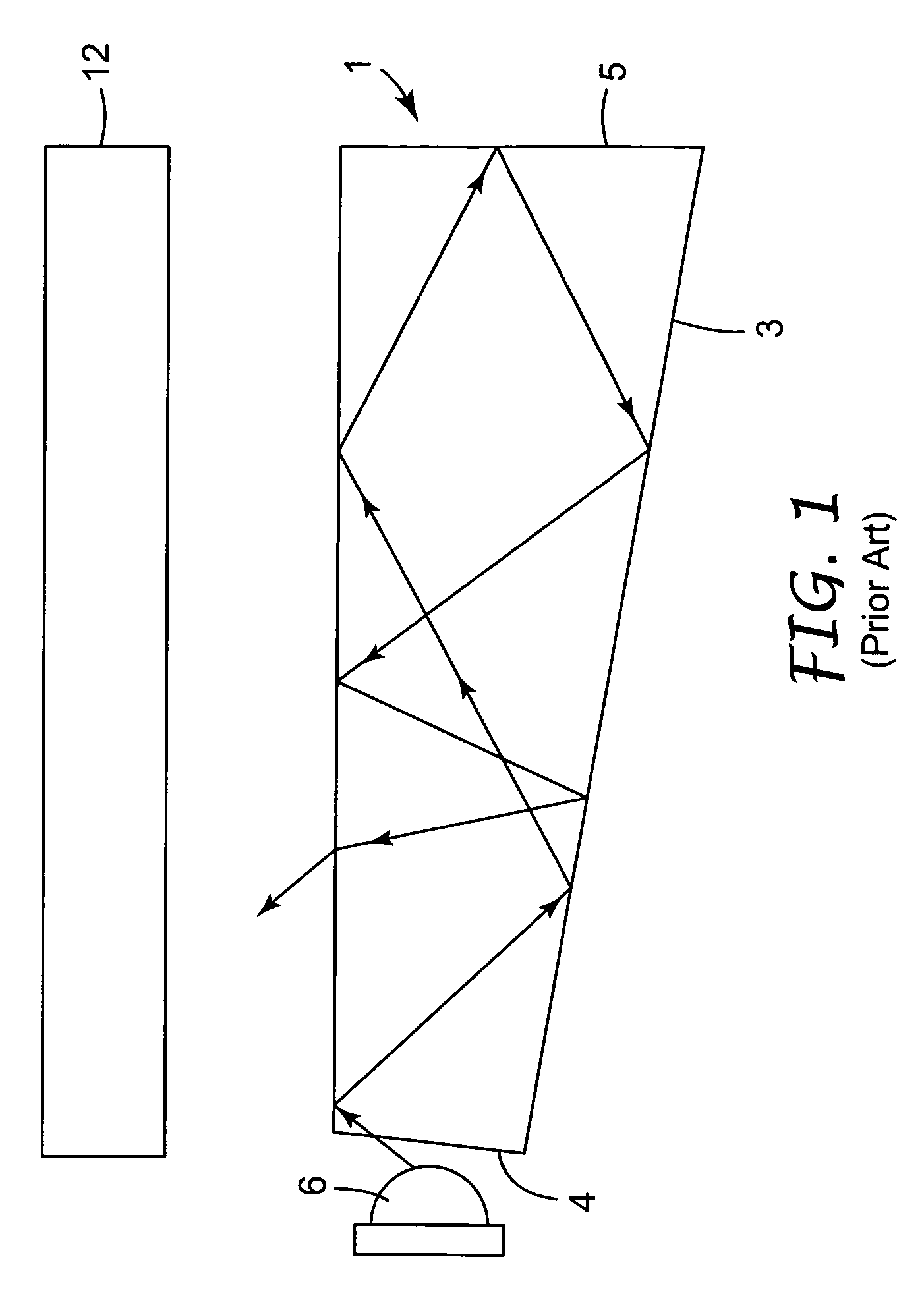
While a number of advantages are associated with LED light sources, they present new challenges for distributing the light uniformly over a surface area.

Method used


Image

  • Illumination device
  • Illumination device
  • Illumination device

Examples


Embodiment Construction

[0034]The present application is directed generally to lighting systems. More particularly, the present invention is directed to an improved illumination system. The illumination system has the ability to provide uniform lighting over a surface area. Light from multiple light sources such as LEDs can be mixed in order to improve lighting uniformity or to mix colors from different colored light sources to produce a desired illumination of blended colors, e.g., white.

[0035]In accordance with one aspect of the present invention, a light guide is provided which includes extracting structures provided on a surface of the light guide. The light guide and the structures cooperatively interact to improve the uniformity (and mixing) of light in and extracted from the light guide. In accordance with one particular embodiment of the invention, the lighting system includes an input area through which light is introduced into a light guide. Light introduced into the light guide propagates betwee...


PUM


Abstract

An illumination system includes a light guide for distributing light. Extraction structures are provided to uniformly extract light from the light guide. The structures extract more light out of the light guide when light is propagating in the light guide in a direction toward the light input area than when light is propagating in the light guide in a direction away from the light input area.

Description

FIELD OF THE INVENTION[0001]This invention relates generally to illumination devices. In particular, the invention relates to illumination devices having a light guide wherein light is extracted out of the light guide differently depending on the direction of light propagation in the light guide.BACKGROUND OF THE INVENTION[0002]In the field of lighting, there are a number of applications that call for lighting systems that illuminate large surface areas. In many of these lighting systems, it is desirable to have the distance between the light source and the illuminated object as small as possible. It is therefore desirable to provide a uniform illumination system that is thin and that can be made at an acceptable cost.[0003]One such lighting system, commonly referred to as an edge lit system, uses a light guide to distribute light, introduced into the light guide at an edge of the light guide, over a relatively large surface area. Such systems are used commonly as backlights for dis...

Claims


Application Information

Patent Timeline
Patent Type & Authority Patents(United States)
IPC IPC(8): F21V7/04F21V8/00G02B6/00
CPCG02B6/0038G02B6/0061G02B6/0068
Inventor EPSTEIN, KENNETH A.WHITNEY, LELAND R.HOYLE, CHARLES D.KRETMAN, WADE D.
Owner 3M INNOVATIVE PROPERTIES CO
Learn More