
Self-aligning blade angle guide

a self-aligning, blade technology, applied in the direction of cutting tools, other manufacturing equipment/tools, manufacturing tools, etc., can solve the problems of requiring a great deal of skill, blades must be unclamped, removed, turned over and re-clamped to sharpen the opposite side, etc., to achieve the effect of minimal effort and minimal opportunity for error

Inactive Publication Date: 2006-05-30
SWARTZ RONALD
View PDF36 Cites 24 Cited by
  • Summary
  • Abstract
  • Description
  • Claims
  • Application Information

AI Technical Summary

Benefits of technology

[0028]6) will enable the user, regardless of skill, knowledge or experience, to sharpen b

Problems solved by technology

While in theory, the actions involved in the process of sharpening are fairly simple, in practice a good deal of skill is required, and sharpening has been a difficult task for the average person.
Defects and deformities are removed and a clean smooth surface is created.b) As the underside of the blade edge is ground away, microscopic burrs and filings are formed on the opposite or “top” side of the edge.These burrs and filings are detrimental to the desired effect of sharpening and continue to build up with each pass across the abrasive surface.
Again, this devise does maintain a fixed angle between the blade and the sharpening surface but, the drawback of this system is that the blade must be unclamped, removed, turned over and re-clamped to sharpen the opposite side.
This makes the process of sharpening more difficult and time-consuming than necessary.
Further, passing the stone alternately over each side of the blade is impractical.
Achieving uniform blade-to-stone contact on both sides of the blade is difficult because the blade must be precisely positioned in the clamp, and any misalignment or structural anomaly of the clamp will result in a portion of the blade edge being held above the surface of the whetstone.
Additionally, the clamp body rides the surface of the stone, which wears the device itself and clogs the porous surface of the sharpening stone with additional metal filings.

Method used


Image

  • Self-aligning blade angle guide
  • Self-aligning blade angle guide
  • Self-aligning blade angle guide

Examples


Embodiment Construction

Description—FIGS. 1–10—Preferred Embodiment

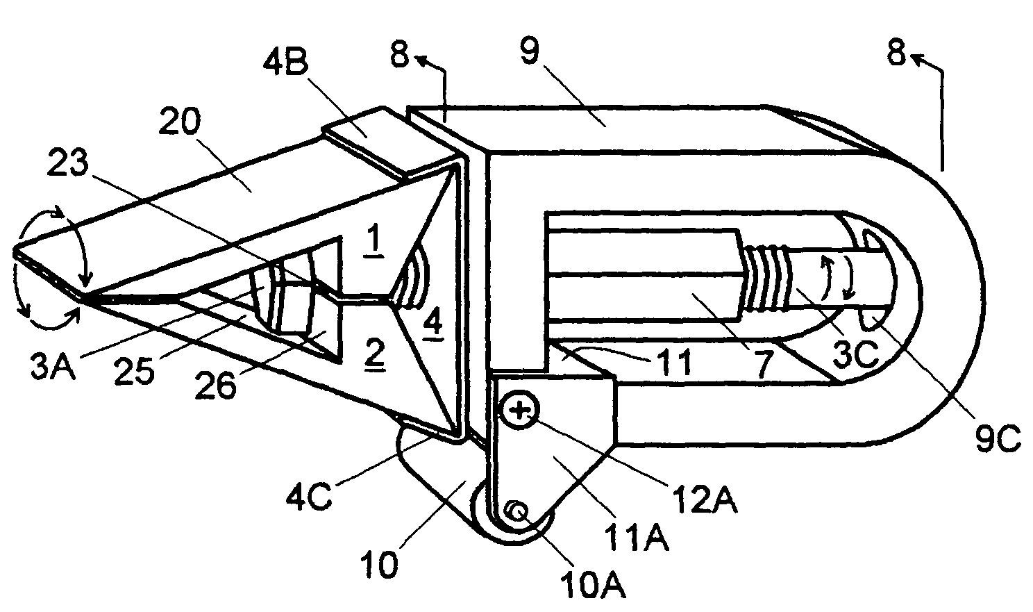
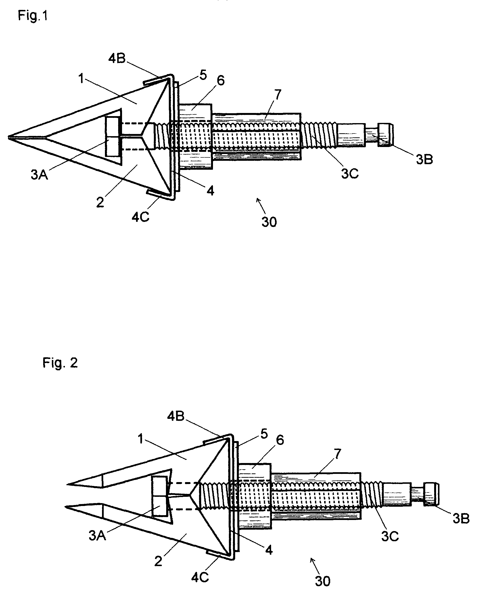
[0041]A preferred embodiment of the self-aligning blade angle guide includes: a clamp and axle assembly 30, (FIGS. 1 and 2) which is designed to interchangeably retain one of two matched pairs of special purpose jaw members. Each matched pair differs in configuration and purpose.

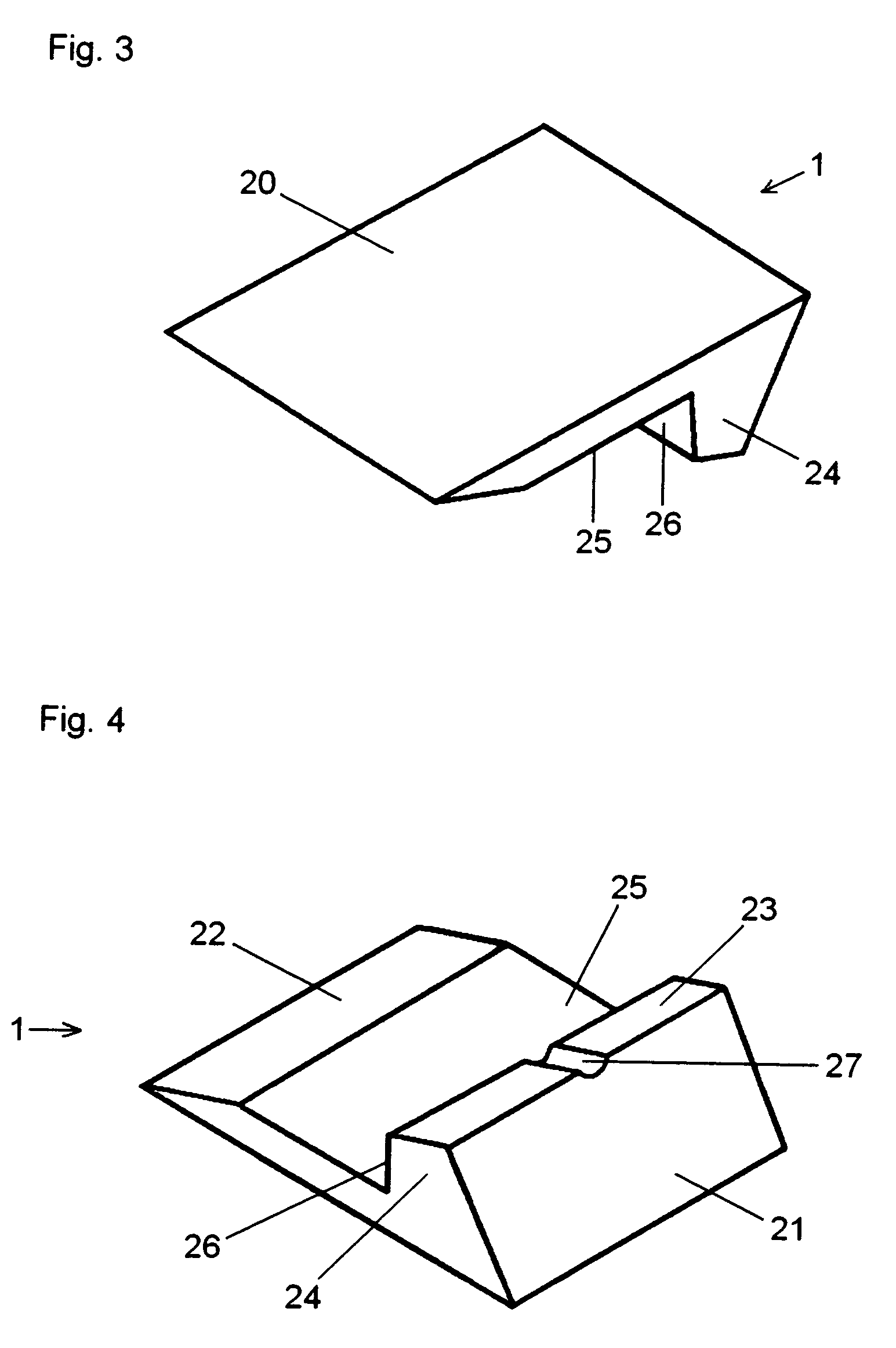
[0042]A first pair of jaw members 1, 2 (FIGS. 3 and 4) is designed to grip razor blades and other small flat bodied blades.

[0043]A second pair of jaw members 13, 14 (FIGS. 5 and 6) is designed to grip arrow broadheads.

[0044]Either pair of jaw members 1, 2 (FIGS. 3 and 4) or 13, 14 (FIGS. 5 and 6) may be selectably installed in the clamp and axle assembly 30 by the user, depending on the type of blade to be sharpened.

[0045]The clamp and axle assembly 30 further includes a bolt 3 having at its first end a bolt head 3a, which is standard hexagonal in configuration. Extending from the bolt head 3a is a threaded bolt shaft 3c. Mounted on the bolt shaft 3c is a base plate...


PUM

PropertyMeasurementUnit
Angleaaaaaaaaaa
Lengthaaaaaaaaaa
Angleaaaaaaaaaa

Abstract

A device for use in the manual sharpening of arrow broadheads, razor blades and the like includes a unique symmetrical clamp and axle assembly having interchangeable, matched pairs of special purpose jaw members for gripping blades of differing configurations. When coupled to the frame, the clamp and axle assembly is freely rotatable, and this free rotation automatically aligns the length of the edge of the blade with the surface of a whetstone. Additionally these rotational and self-aligning capability enable the user to service both sides of the blade's edge with a single blade clamping operation, by manually rotating the clamp 180 degrees between passes along the surface of the whetstone.

Description

FEDERALLY SPONSORED RESEARCH[0001]Not ApplicableSEQUENCE LISTING OR PROGRAM[0002]Not ApplicableBACKGROUND[0003]1. Field of Invention[0004]This invention is an improved device for use in the manual sharpening of arrow broadheads, razor blades, and specialty blades.[0005]2. Discussion of Prior Art[0006]The need to sharpen or re-sharpen blades of cutting instruments is ancient. While in theory, the actions involved in the process of sharpening are fairly simple, in practice a good deal of skill is required, and sharpening has been a difficult task for the average person. This is particularly true of smaller blades. This is evidenced by the countless devices that have been designed to aid the user in the process of sharpening, and by the fact that entire industries exist solely to manufacture disposable blades of widely varying style and purpose.[0007]The vast array of prior art devices for aiding in the manual sharpening of blades generally have had a common goal, which is to maintain ...

Claims


Application Information

Patent Timeline
IPC IPC(8): B24B19/00
CPCB24B41/06B24B3/00
Inventor SWARTZ, RONALD
Owner SWARTZ RONALD
Learn More