Prosthetic leg and foot apparatus

a technology for applied in the field of prosthetic legs and foot devices, can solve the problems of difficulty in walking without shoes, difficulty in downhill walking, and a certain work effor

Inactive Publication Date: 2006-05-30
GRAMTEC INNOVATION
View PDF26 Cites 45 Cited by
  • Summary
  • Abstract
  • Description
  • Claims
  • Application Information

AI Technical Summary

Benefits of technology

[0009]This aim is achieved by means of a device in a leg prosthesis provided with a foot, which is connected to the leg prosthesis via an articulated axle, whereby first means are arranged to allow a limited rotation of the foot relative the leg prosthesis from an initial position, in which position the leg prosthesis and the foot have a fixed angle relative each other, and second means are arranged to provide a step-less adjustment of the fixed angle between the leg prosthesis and the foot in the initial position, characterized in that the first means comprise a resilient element, which first end thereof is connected to the foot via a elongated element and which second end is connected to the leg prosthesis so that the leg prosthesis can be rotated relative the foot against the effect of the spring force of the resilient element.

Problems solved by technology

It is well known among prosthesis wearers that downhill walking is problematic.
Therefore, prosthesis wearers often choose to walk sidewards when walking downhills.
Further, prosthesis wearers utilizing a foot prosthesis which is not vertically adjustable have problems changing to another shoe with a different heel height, and have difficulty walking without shoes.
The prosthesis wearer must turn the screw a number of turns to change the angle position, which requires a certain work effort.
The principle of changing the angle shown in this document has the great disadvantage that the length of the leg changes, which results in that the prosthesis wearer can have one leg shorter or longer than the other in certain situations.

Method used


Image

  • Prosthetic leg and foot apparatus
  • Prosthetic leg and foot apparatus
  • Prosthetic leg and foot apparatus

Examples


Embodiment Construction

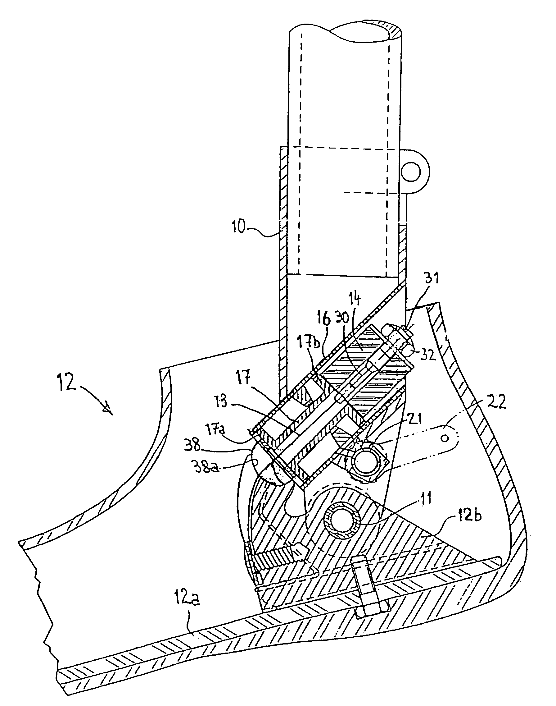
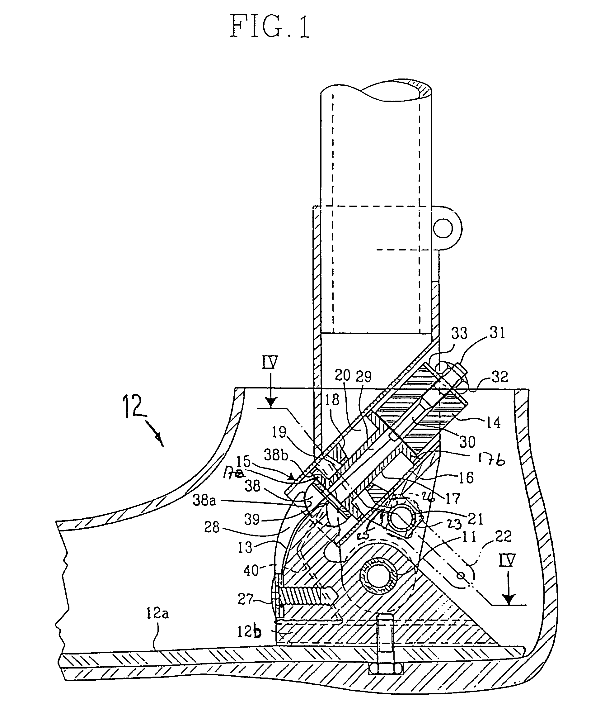
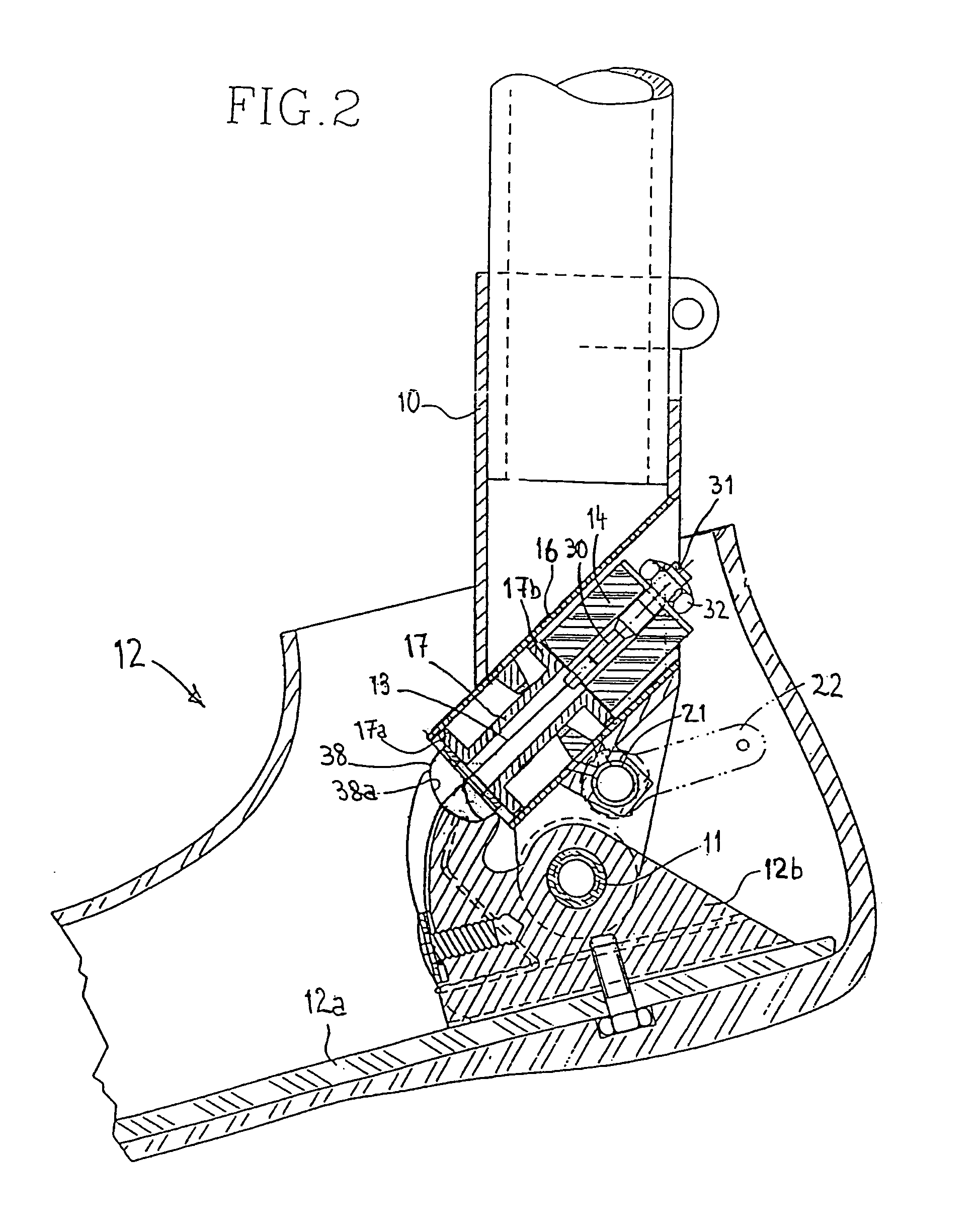
[0016]The Figures show a leg prosthesis 10 in the form of cylindrical tube frame, which via an articulated axle 11, forming an ankle joint, is connected to a portion 12b of a foot 12. The foot 12 can be provided with a foot blade 12a, which can be provided with foot cosmetics. The elongate element 13, in the form of a cord, wire, belt or the like, is eccentrically attached to the portion 12b of the foot relative its articulated axle 11. The elongate element 13 runs through a central channel 29 running through a piston 17 and is attached to a nipple 30 with its second end, which nipple 30 extends through a central passage in resilient element 14. A screw 31 is threaded into the nipple 30 and a nut 32 is screwed on the outside of the screw. Preferably, a washer 33 of metal or other rigid material is provided between the nut 32 and the resilient element 14. Suitably, the elongate element 13 has such a length that the resilient element 14 is restrained between one end 17b of the piston ...


PUM


Abstract

The present invention relates to an arrangement for a leg prosthesis (10) provided with a foot (12), which is connected to the leg prosthesis via an articulated axle (11), whereby first means (13, 14, 16–18, 30–33, 38) are arranged to provide a limited rotation of the foot relative the leg prosthesis from an initial position, in which position the leg prosthesis and the foot have a fixed angle relative each other, and second means (16–26) are arranged to provide a step-less adjustment of the fixed angle between the leg prosthesis and the foot in the initial position. According to the invention the first means (13, 14, 16–18, 30–33, 38) comprise a resilient element (14), which first end thereof is connected to the foot (12) via an elongated element (13) and which second end is connected to the leg prosthesis so that the leg prosthesis can be rotated relative the foot against the effect of the spring force of the resilient element.

Description

TECHNICAL FIELD[0001]The present invention relates to a device in a leg prosthesis provided with a foot, which is connected to the leg prosthesis via an articulated axle, whereby first means are arranged to provide a limited rotation of the foot relative the leg prosthesis from an initial position, in which position the leg prosthesis and the foot have a fixed angle relative each other, and second means are arranged to provide a step-less adjustment of the fixed angle between the leg prosthesis and the foot in the initial position.BACKGROUND OF THE INVENTION[0002]It is well known among prosthesis wearers that downhill walking is problematic. If the prosthesis wearer does not have the possibility of adjusting the angle of the foot, the walk downhill gets such that only the heel has contact with the ground. Above a certain degree of foot angle it is difficult to bear up the body weight so that the knee does not collapse because of the lack of essential groups of muscles. Therefore, pr...

Claims


Application Information

Patent Timeline
Patent Type & Authority Patents(United States)
IPC IPC(8): A61F2/66A61F2/50
CPCA61F2/6607A61F2002/5003A61F2002/745A61F2002/5016A61F2002/5007A61F2/74
Inventor GRAMNAS, FINN
Owner GRAMTEC INNOVATION
Why Eureka
Try Eureka