Light-emitting device with improved brightness control and narrow frame and electronic apparatus with the light-emitting device

a technology of light-emitting devices and electronic devices, which is applied in the direction of static indicating devices, discharge tubes luminescnet screens, instruments, etc., can solve the problems of difficulty in mounting light-emitting elements on various electronic devices, and achieve the effect of narrowing the fram

Active Publication Date: 2006-05-30
INTELLECTUAL KEYSTONE TECH LLC
View PDF14 Cites 32 Cited by
  • Summary
  • Abstract
  • Description
  • Claims
  • Application Information

AI Technical Summary

Benefits of technology

[0008]In view of the above and / or other difficulties, the present invention secures a sufficient amount of current or prevents a change in the brightness of the light-emitting element due to change in power source voltage. The present invention also provides a light-emitting device and an electronic apparatus capable of satisfying the above necessities and of narrowing the frame.

Problems solved by technology

Therefore, it is difficult to mount light-emitting elements on various electronic apparatuses.

Method used


Image

  • Light-emitting device with improved brightness control and narrow frame and electronic apparatus with the light-emitting device
  • Light-emitting device with improved brightness control and narrow frame and electronic apparatus with the light-emitting device
  • Light-emitting device with improved brightness control and narrow frame and electronic apparatus with the light-emitting device

Examples


Embodiment Construction

[0040]An exemplary embodiment of a light-emitting device according to the present invention is described below.

[0041]As shown in FIG. 4, in a light-emitting device 1 according to the present exemplary embodiment, a plurality of scanning lines 101, a plurality of data lines 102 extended to a direction crossing the scanning lines 101 and a plurality of display power source lines 103 extended in parallel for the data lines 102 are wired respectively.

[0042]Pixel areas A are formed in portions where the scanning lines 101 cross the data lines 102.

[0043]A data driving circuit 104 having a shift register, a level shifter, a video line and an analog switch is connected to the data lines 102. A scan driving circuit 105 having the shift register and the level shifter is connected to the scanning lines 101.

[0044]Each pixel area A includes a switching thin film transistor 122 to supply scanning signal to a gate electrode through the scanning lines 101, a storage capacitor cap to store pixel sig...


PUM


Abstract

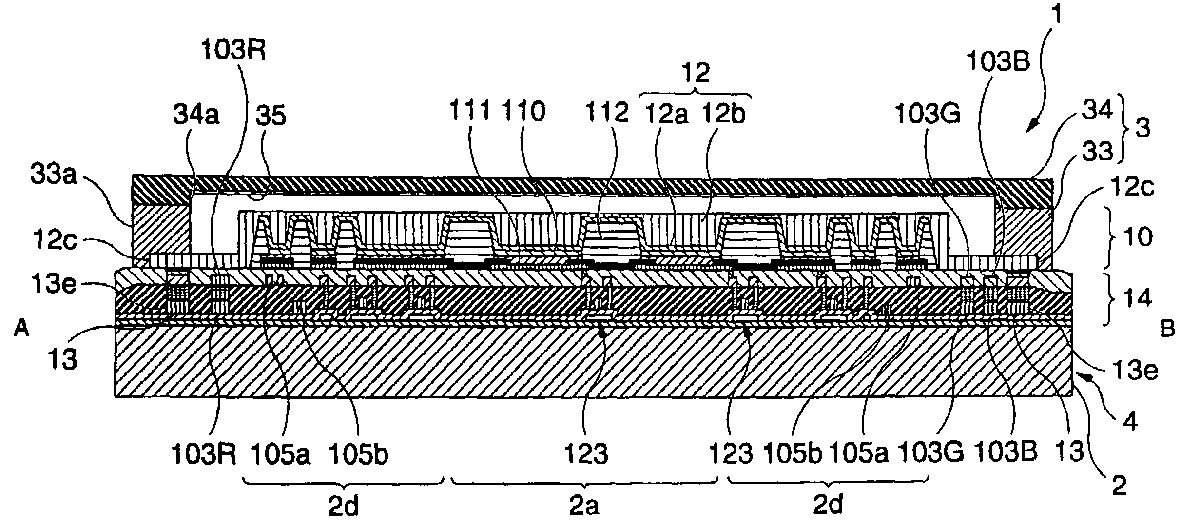
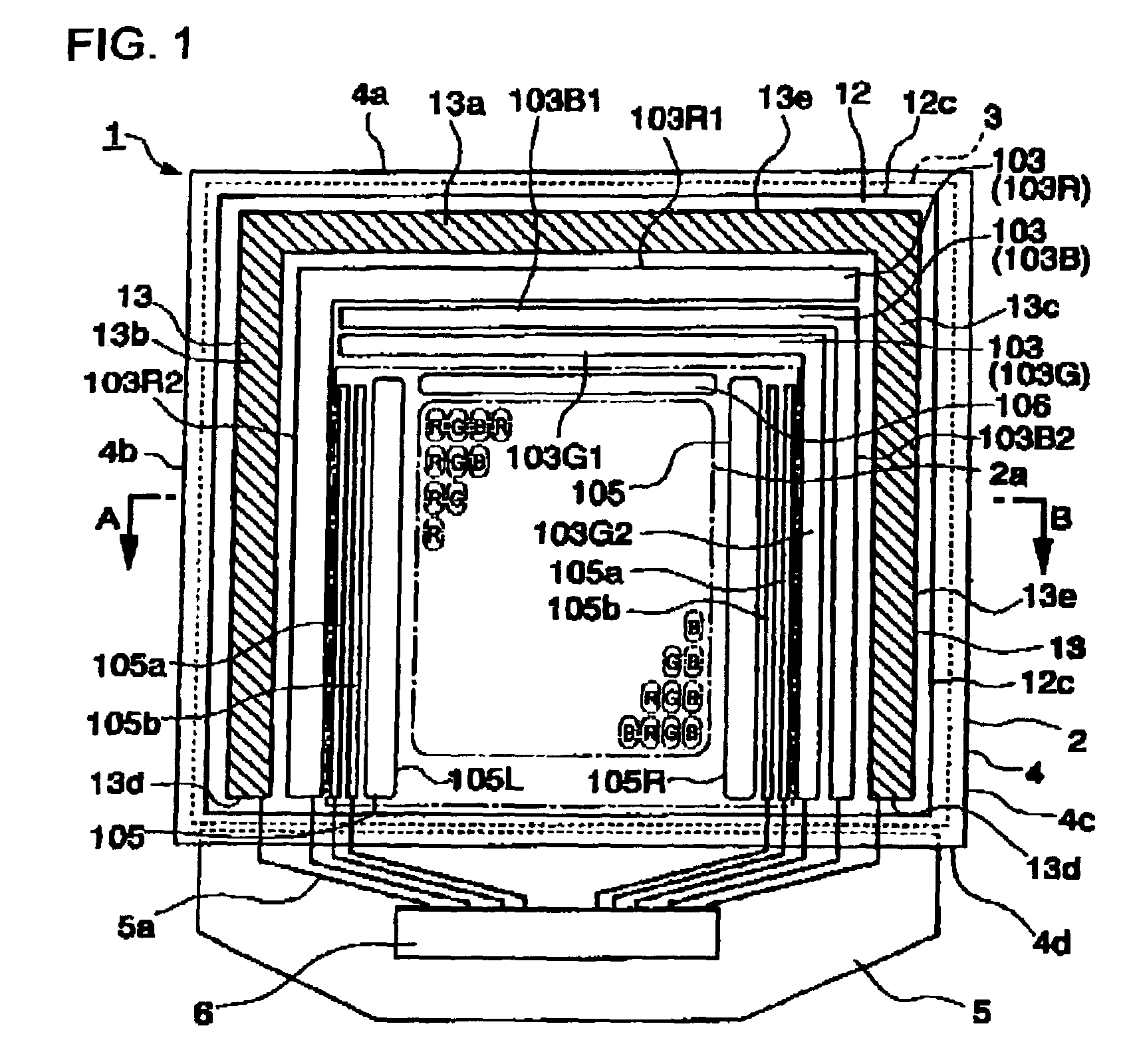
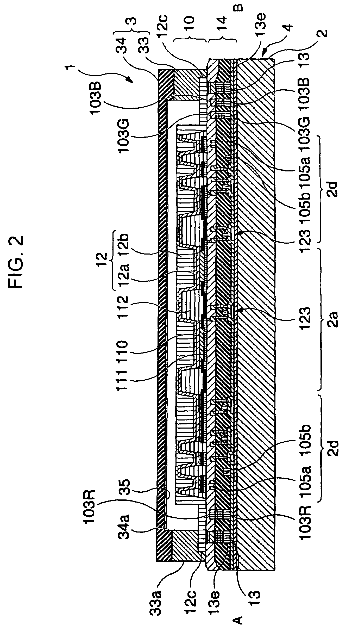
The invention provides a light-emitting device and an electronic apparatus, which are capable of preventing reduction of the amount of current flowing through light-emitting elements and which have an excellent display characteristic. Cathode wiring lines connected to a cathode are provided to surround an effective area outside the effective area where a plurality of pixels having light-emitting elements are provided. First to third power source lines 103G, connected to pixel electrodes are provided between the cathode wiring lines and the effective area.

Description

BACKGROUND OF THE INVENTION[0001]1. Field of Invention[0002]The present invention relates to a light-emitting device and an electronic apparatus using the same.[0003]2. Description of Related Art[0004]Related art organic electroluminescence (EL) display devices having light-emitting elements using an organic-light-emitting material between a substrate, in which pixel electrodes are formed, and a counter electrode, are disclosed in Gazette of Japanese Unexamined Patent Application Publication No. 5-3080.[0005]In the organic EL display devices, the light-emitting elements emit light by supplying current to the light-emitting elements. At that time, the brightness of the light-emitting element is determined by the amount of current basically supplied thereto.[0006]It is necessary to accurately set the amount of current to have a desired value because the brightness of such light-emitting elements is basically determined by the amount of supplied current.[0007]In order to secure a suffi...

Claims


Application Information

Patent Timeline
Patent Type & Authority Patents(United States)
IPC IPC(8): H01J1/62G09G3/10H05B33/06G09G3/30H01L27/32H01L33/26H01L33/44H01L51/50H01L51/52H05B33/10H05B33/12H05B33/14H05B33/26
CPCH01L27/3276H01L51/5246H05B33/06H01L27/3211Y10S428/917H01L51/5221H10K59/35H10K59/131H10K50/82H10K50/8426
Inventor NAKANISHI, HAYATO
Owner INTELLECTUAL KEYSTONE TECH LLC
Why Eureka
Try Eureka