Multi-band antenna system

a multi-band antenna and antenna earthing technology, applied in the direction of resonant antennas, antenna earthings, radiating element structural forms, etc., can solve the problems of expensive and awkward device use, and achieve the effect of high impedan

Active Publication Date: 2006-05-30
NETGEAR INC
View PDF12 Cites 22 Cited by
  • Summary
  • Abstract
  • Description
  • Claims
  • Application Information

AI Technical Summary

Problems solved by technology

Indeed, the cellular telephone, which was an expensive and awkward device to use just a couple of decades ago, has become commonplace in today's world.

Method used


Image

  • Multi-band antenna system
  • Multi-band antenna system
  • Multi-band antenna system

Examples


Embodiment Construction

[0017]Embodiments of the present invention relate to multi-band antenna systems capable of receiving signals from different frequency bands and / or signals from wireless networks defined by competing wireless network technologies. Those of ordinary skill in the art will realize that the following detailed description of the present invention is illustrative only and is not intended to be in any way limiting. Other embodiments of the present invention will readily suggest themselves to such skilled persons having the benefit of this disclosure. Reference will now be made in detail to implementations of the present invention as illustrated in the accompanying drawings. The same reference indicators will be used throughout the drawings and the following detailed description to refer to the same or similar parts.

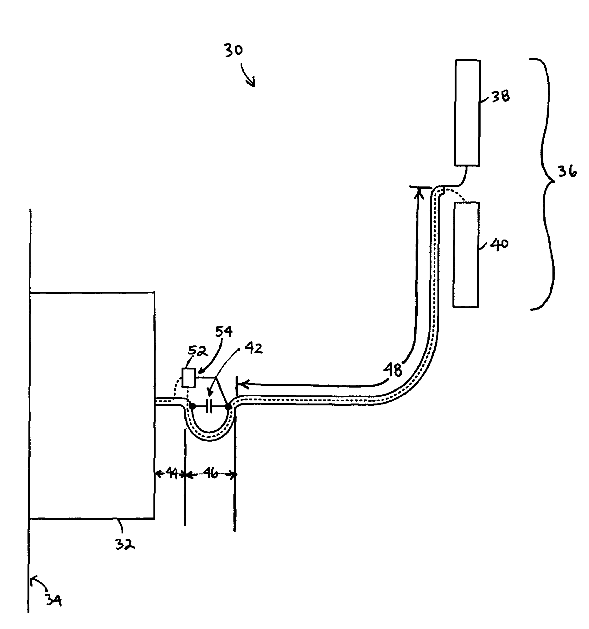
[0018]FIG. 3 shows a multi-band antenna system 30, according to an embodiment of the present invention. The multi-band antenna system 30, as well as the other multi-band antenna ...


PUM


Abstract

A multi-band antenna system for a portable communications device (e.g. a PC Card wireless modem) is disclosed. The multi-band antenna system comprises a dipole antenna, a reactive circuit, and transmission means coupled between the reactive circuit and the dipole antenna. For signals having frequencies within a first frequency band (e.g. the CDMA 0.86 GHz band), the reactive circuit operates as a trap, i.e. as a substantially high impedance, which enables a radiation impedance of a monopole formed by the presence of the trap to be coupled directly into the feed system (e.g. a diplexer) of the antenna system. The dipole antenna is configured and dimensioned to receive signals within a second frequency band (e.g. the PCS 1.92 GHz band). Second frequency band signals received by the dipole antenna are conducted through the signal conductor of the transmission means to the feed system substantially unimpeded by the reactive circuit. The multi-band antenna system may further include a diversity antenna, which may be configured so that it is polarized orthogonal the to dipole antenna.

Description

FIELD OF THE INVENTION[0001]The present invention relates to antennas for receiving radio frequency (RF) signals. More particularly, the present invention relates to multi-band antenna systems capable of receiving signals from different frequency bands and / or signals from wireless networks defined by competing wireless network technologies.BACKGROUND OF THE INVENTION[0002]The development, deployment and refinement of wireless communication systems and devices have increased dramatically over recent years. Indeed, the cellular telephone, which was an expensive and awkward device to use just a couple of decades ago, has become commonplace in today's world. Communicating wirelessly is desirable since it allows user mobility and provides a user, in most respects, the ability to establish communications with another user irrespective of knowledge of the other user's location.[0003]The prospect that the mobile nature of wireless communications would extend from just voice communications t...

Claims


Application Information

Patent Timeline
Patent Type & Authority Patents(United States)
IPC IPC(8): H01Q1/24H01Q1/22H01Q1/38H01Q5/00H01Q5/15H01Q5/335H01Q9/16H01Q9/20
CPCH01Q1/2275H01Q5/335H01Q9/20H01Q5/00
Inventor NYSEN, PAUL A.
Owner NETGEAR INC
Why Eureka
Try Eureka