Process for regulating the exposure time of a light sensor

a light sensor and exposure time technology, applied in the field of light sensor exposure time regulation, can solve the problems of inability to detect details having small sizes, low resolution acquisition of images on the sensor, and inability to detect details with small sizes, so as to avoid conditions of strong saturation of images and increase image resolution

Inactive Publication Date: 2006-05-30
DATALOGIC
View PDF20 Cites 45 Cited by
  • Summary
  • Abstract
  • Description
  • Claims
  • Application Information

AI Technical Summary

Benefits of technology

[0017]We are talking therefore about a process for selecting an exposure time which is thought to be optimum, and that is which avoids conditions of strong saturation of the image on the sensor in the presence of an increase of the environmental light and, at the same time, conditions of under-exposure of the image in the presence of a decrease of environmental light. Advantageously, finding the right exposure time occurs by successive approximation, each time evaluating whether the image presents an undesired characteristic which results to be too much elevated (such as for example the excessive saturation or under-exposure) and suitably varying the exposure time of the sensor so as not to provoke the arise of such characteristic; it is therefore possible to regulate in real time the light sensor according to the variations of luminosity of the surrounding environmental and of the surface to be acquired.
[0018]More in particular, where the characteristic evaluated is the excessive saturation, the optimum exposure time found is, advantageously, the maximum possible exposure time compatible with the absence of conditions of saturation of the image; this allows to assure an elevated resolution of the image acquired on the sensor, without provoking its saturation.
[0019]In alternative, where the characteristic evaluated is the excessive under-exposure, the optimum exposure time found is, advantageously, the minimum possible exposure time compatible with the absence of conditions of under-exposure of the image; this allows to avoid the risk of having, on one side, images which are too dark and without details and, on the other side, blurred images (for example, in the case in which the reader is of a portable or manual type).
[0020]The duration of the process depends on the number of values of exposure time which the sensor can assume. Advantageously, from this set of values a smaller range of M values is chosen, which are thought to be particularly interesting; this allows the end of the process of determination of the optimum exposure time of the sensor to be reached quicker.

Problems solved by technology

As is known, a drawback associated with light sensors at present available on the market is correlated to the fact that their operation is strongly influenced by the variations in luminosity of the surface on which the image to be acquired is to be found (such surface can be more or less clear and more or less illuminated).
In both cases, the image acquired by the sensor appears badly exposed and not very clear, therefore making it impossible to detect details having small sizes.
In particular, with reference to the reading of an optical code, the acquisition on the sensor of an image of an optical code having a low resolution is often undesired because it renders the subsequent operations of localization, reading and decoding of the code itself very approximate and rough; this is absolutely unacceptable where it is necessary to carry out a correct decoding of the code in order to unequivocally identify the object having the code thereon.

Method used


Image

  • Process for regulating the exposure time of a light sensor
  • Process for regulating the exposure time of a light sensor
  • Process for regulating the exposure time of a light sensor

Examples


Embodiment Construction

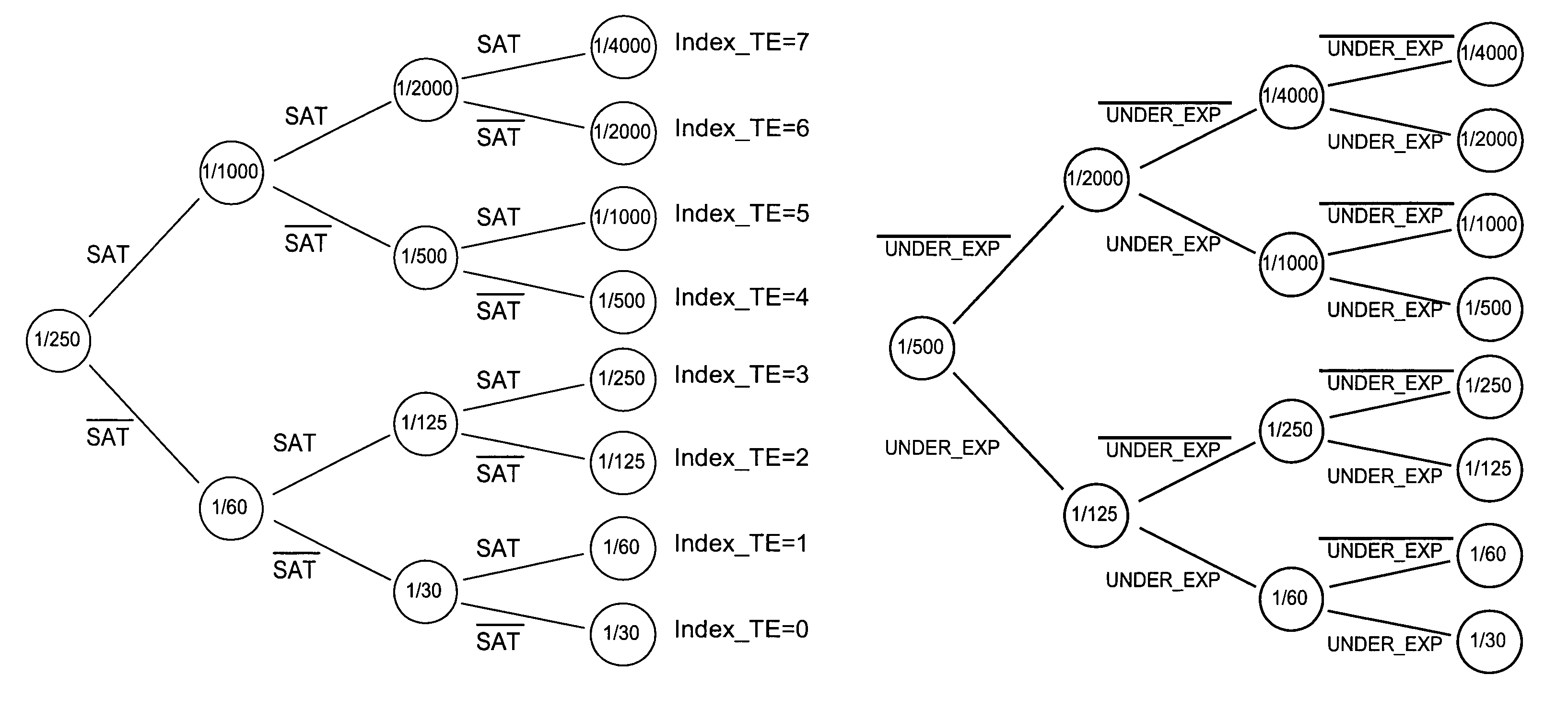
[0059]The process of the invention allows, by successive approximations, the determination of an optimum exposure time according to the variations of luminosity of the surface on which the image to be acquired is to be found and of the environment in which the light sensor is located (for example, a CCD or CMOS sensor, whether linear or of matrix type).

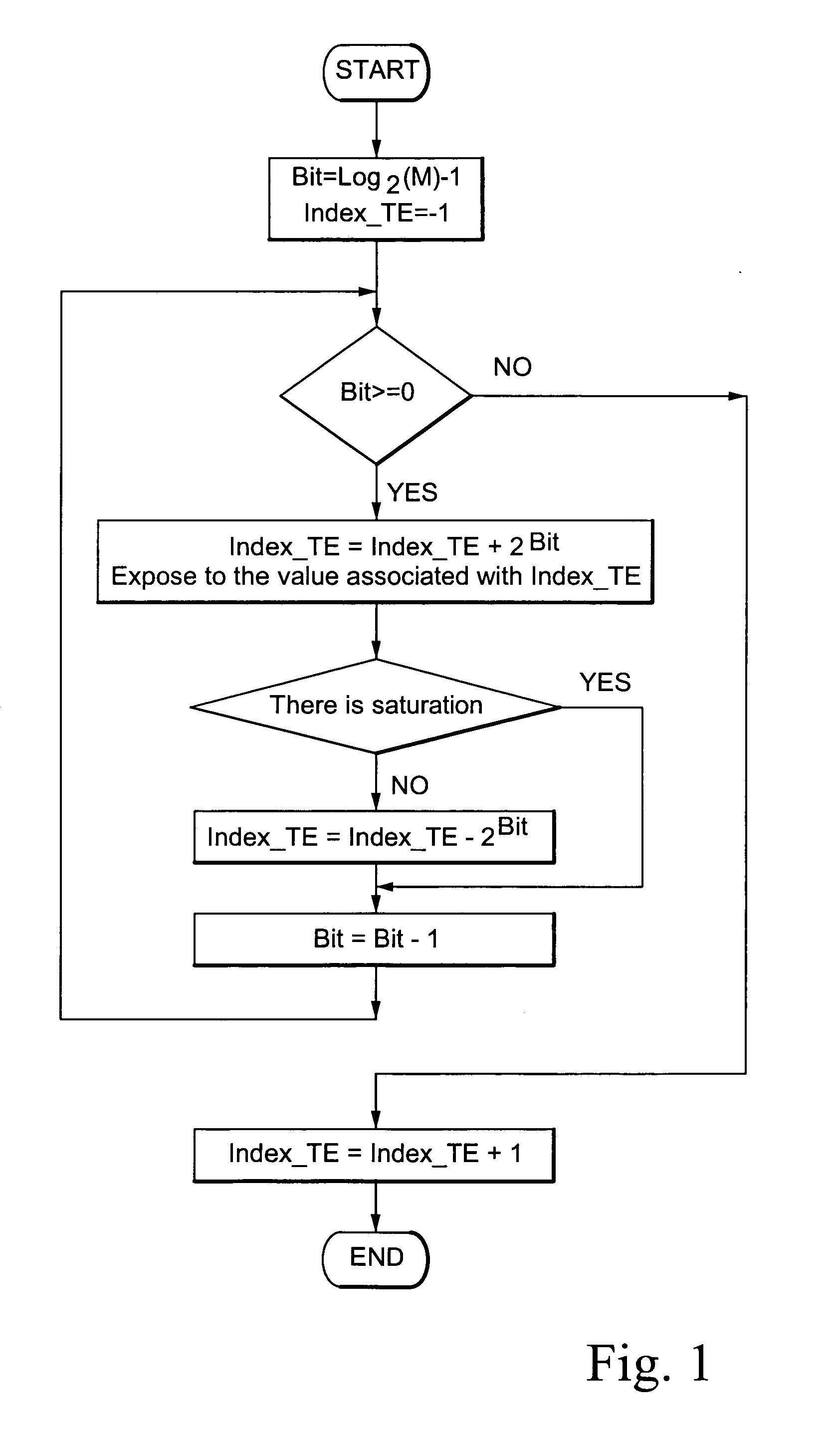
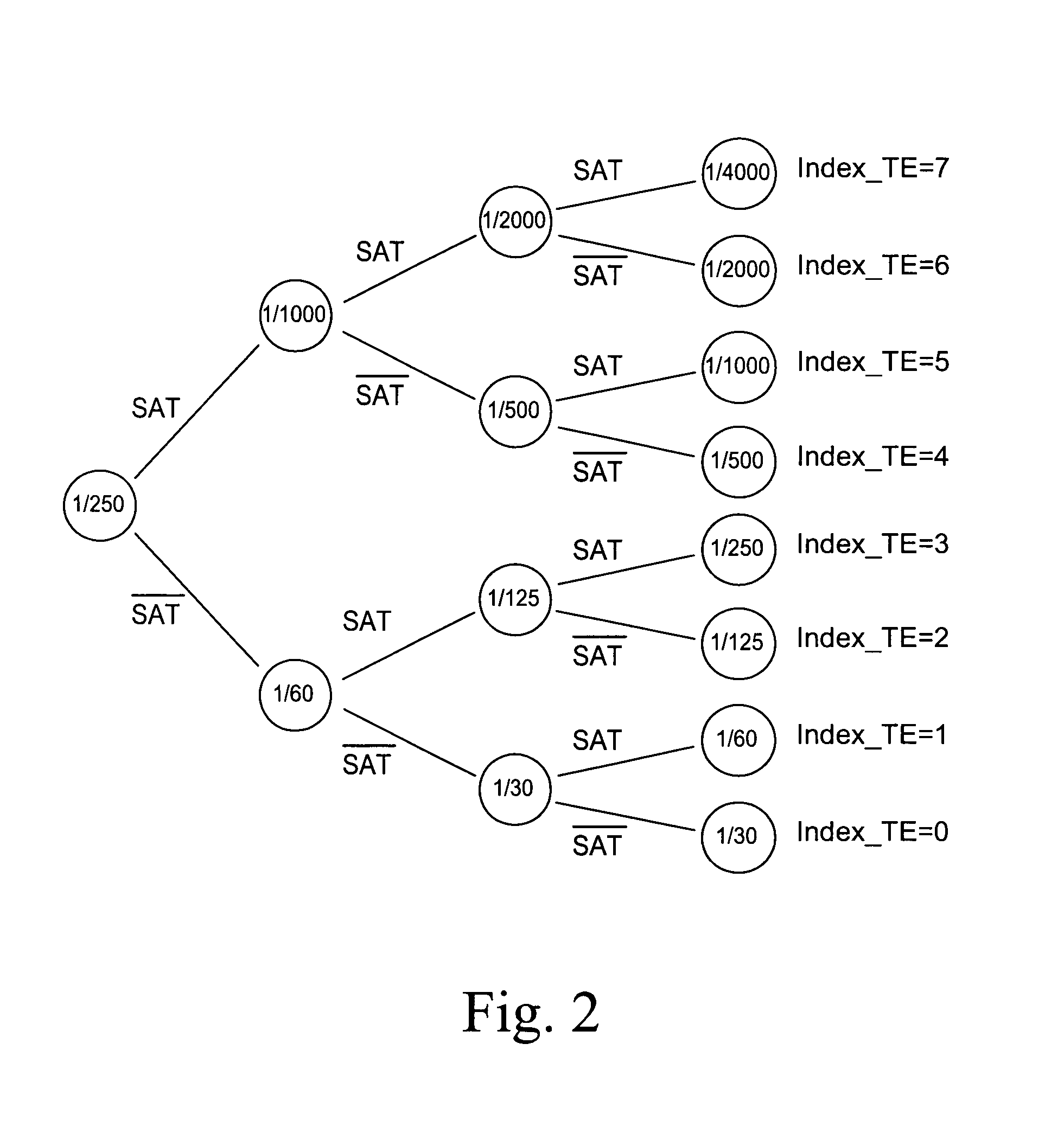
[0060]The process begins with the setting of an initial exposure time in the sensor equal to a value chosen in a first range of M prefixed values which are defined between a minimum value and a maximum value. Advantageously, the M values are a subset, thought to be particularly interesting, of the whole of the settable values of exposure times for the sensor in question and are stated by the manufacturer. In the examples shown in the figures attached, the values of exposure time chosen are eight and are, in fractions of a second: 1 / 30, 1 / 60, 1 / 125, 1 / 250, 1 / 500, 1 / 1000, 1 / 2000, 1 / 4000.

[0061]Once an initial exposure time is set, an ima...


PUM


Abstract

This invention relates to a process for regulating the exposure time of a light sensor, characterized in that it comprises the following steps:
    • a) setting the exposure time of the sensor to a value selected in a first range of M prefixed values defined between a minimum and a maximum value;
    • b) acquiring an image of an object on the sensor, such image comprising a plurality of luminous pixels;
    • c) analyzing the acquired image in order to detect its level of luminosity;
    • d) comparing the detected level of luminosity with a prefixed higher (lower) global threshold level representative of a condition of overexposure (under-exposure) of the image;
    • e) varying the exposure time of the sensor and iteratively repeating the previous steps until an optimum exposure time equal to the highest (lowest) exposure time is found, amongst the ones set, for which the image presents a level of luminosity which is smaller (greater) than the prefixed higher (lower) global threshold level.

Description

BACKGROUND OF THE INVENTION[0001]1. Field of the Invention[0002]The present invention relates to a process for regulating the exposure time of a light sensor. More particularly, the invention relates to a process for regulating the exposure time of a light sensor according to the variation of luminosity in the work environment in which the sensor is located.[0003]2. Discussion of the Prior Art[0004]Throughout the present description and the attached claims, with the term: “light sensor”, it is intended to indicate a light-sensitive optical element capable of converting a light signal, contained in a incident light beam, in an analogic electrical signal proportional to the light intensity of the light itself. In particular, the light sensor transforms the light image of an illuminated object into an electronic image thereof, in order to allow the carrying out of further operations of image processing, such as for example those connected to the reading of an optical code located on th...

Claims


Application Information

Patent Timeline
Patent Type & Authority Patents(United States)
IPC IPC(8): H04N5/235G03B7/00H04N3/14H04N5/335
CPCH04N5/2353H04N23/73
Inventor CANINI, FEDERICO
Owner DATALOGIC
Why Eureka
Try Eureka