Fan tray assembly

Inactive Publication Date: 2006-05-30
UNISYS CORP
View PDF31 Cites 119 Cited by
  • Summary
  • Abstract
  • Description
  • Claims
  • Application Information

AI Technical Summary

Benefits of technology

[0015]To achieve these and other objects, and in view of its purposes, the present invention provides a fan tray assembly. The assembly comprises a module, which houses electronic components that require cooling, and one or more fan trays. The module has an open front, a first side, and a second side including an alignment track. Each fan tray has (1) at least one fan directing air through the module to cool the electronic components when the fan tray occupies a first position in which the fan tray closes the open front of the module and not directing air through the module when the fan tray occupies a second position in which

Problems solved by technology

As a result, these application cards generate a tremendous amount of heat, which must be removed from the chassis to protect the various electronic components within the chassis.
First, electronic chassis typically have strict dimensional requirements, rendering the size and orientation of the fans critical in the attempt to maximize the amount of air flow through the chassis. Fan tray assemblies housed within the chassis occupy valuable space. This drawback is exacerbated because, in an effort to increase the output of the cooling ability of the fans, which is necessary to prevent overheating of the electronic components within the chassis, most conventional designs have relied on the premise that bigger is better and have increased the size of the fans themselves. This premise results in an increase in the space required within the chassis for the fan tray assembly, which is typically not feasible. The premise also creates other problems, including an increase in the weight of the chassis beyond acceptable limits, an increase in the number of parts, and an increase in the cost of production.
Although this feature assures that the fan tray is not displaced without first unplugging the signal and power cabl

Method used


Image

  • Fan tray assembly
  • Fan tray assembly
  • Fan tray assembly

Examples


Embodiment Construction

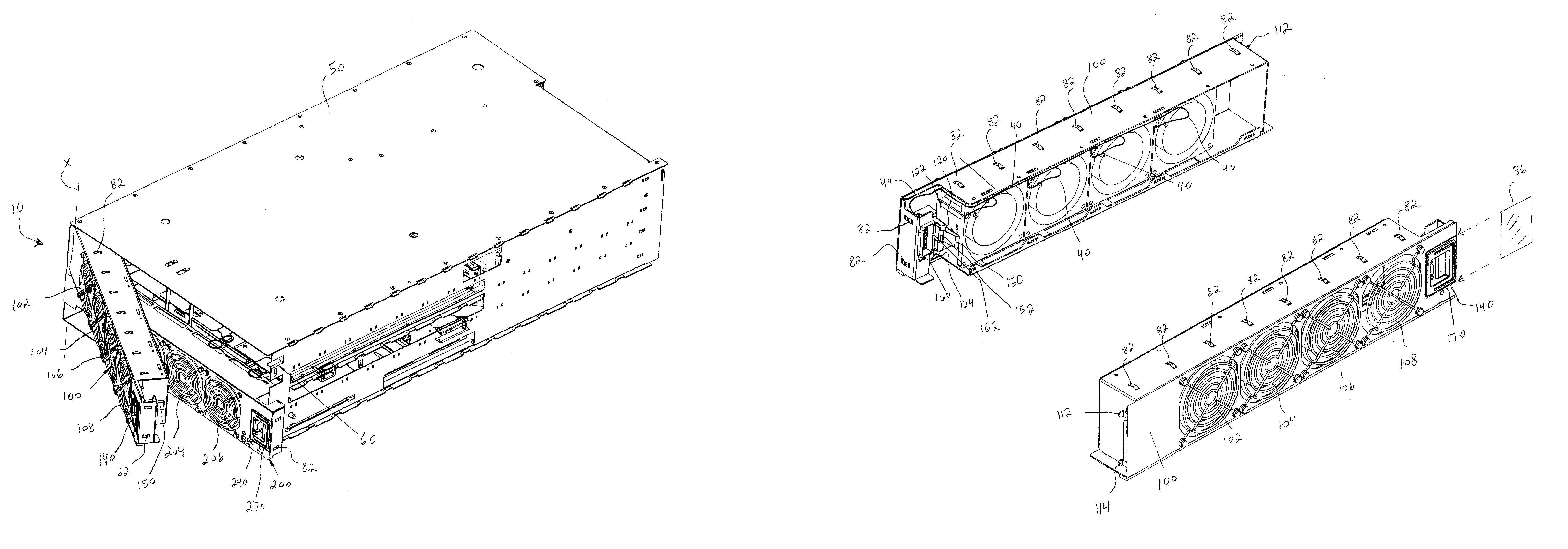
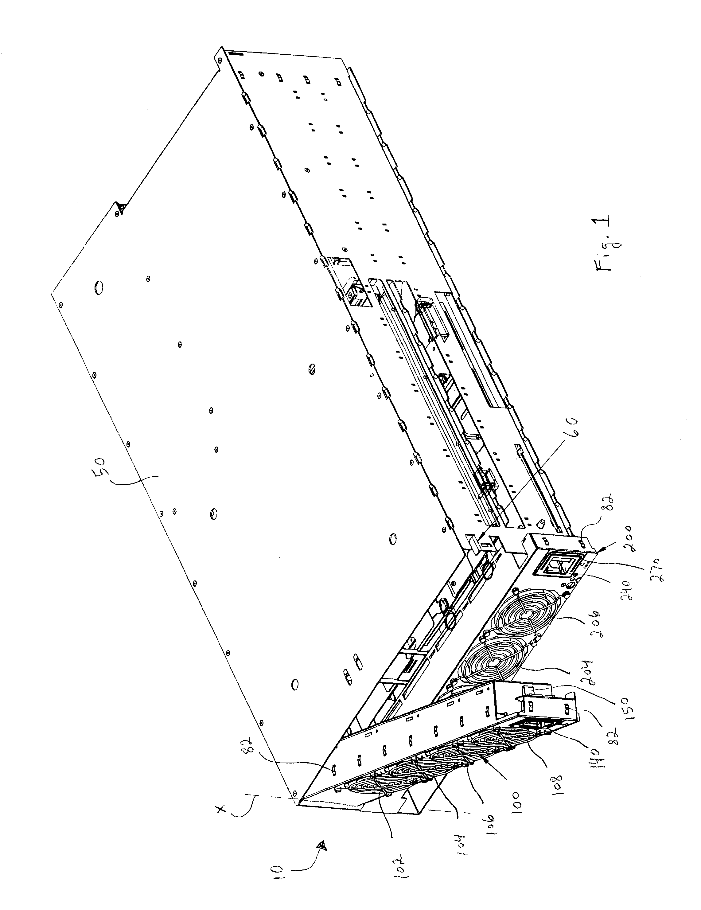
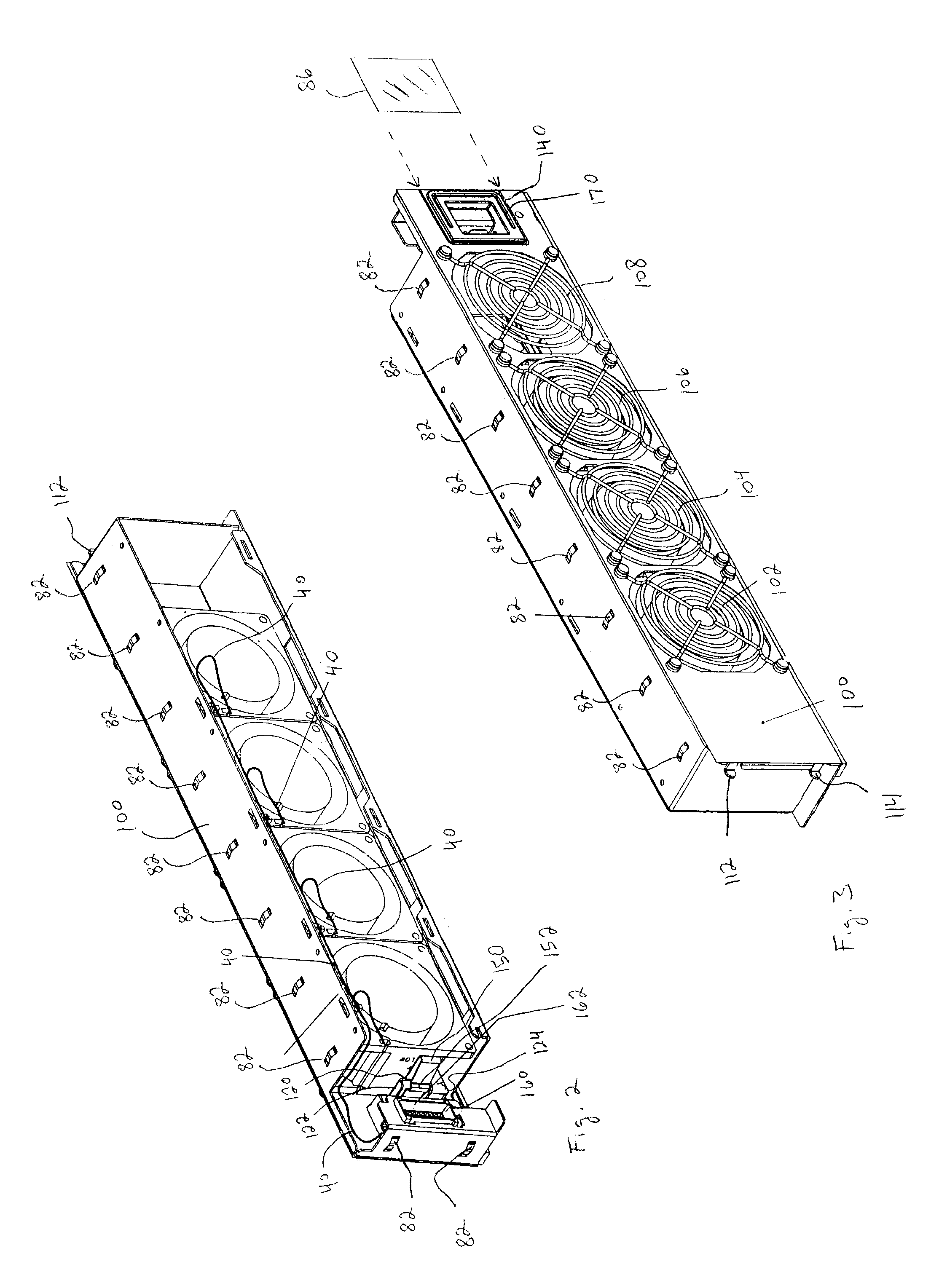
[0029]Referring now to the drawing, in which like reference numbers refer to like elements throughout the various figures that comprise the drawing, FIG. 1 shows a fan tray assembly 10 according to an exemplary embodiment of the invention. The fan tray assembly 10 comprises two separate fan trays: an upper fan tray 100 including four fans 102, 104, 106, 108 is located over a lower fan tray 200 including three fans 202, 204, 206 and a portal 210 that accommodates the insertion of peripheral components (such as instruction cards, drives, and the like) which are not shown. In combination, the two fan trays 100, 200 occupy substantially all of the available front profile or face of the chassis or module 50 to which the fan trays 100, 200 connect. The seven total fans 102, 104, 106, 108, 202, 204, 206 of the fan tray assembly 10 direct air flow (see arrow “A” in FIG. 4) through the module 50.

[0030]Although seven total fans are illustrated in the figures, it should be apparent that any nu...


PUM


Abstract

A fan tray assembly. The assembly comprises a module, housing electronic components that require cooling, and one or more fan trays having fans that direct a cooling air flow through the module. The assembly facilitates easy and fast removal and replacement of the fan trays with respect to the module. These desirable attributes are achieved by five main features of the assembly: (1) a retaining slot-and-tab engagement pivotally attaching each fan tray to one side of the module, (2) a channel-in-track automatically aligning each fan tray as it closes against the module, (3) a leaf spring releasably locking each fan tray into a closed position, (4) a floating power-and-signal connector on each fan tray electrically and mechanically engaging a corresponding receptacle on the module, and (5) a pull ring facilitating manipulation of each fan tray.

Description

FIELD OF THE INVENTION[0001]The present invention relates generally to computer systems and, more particularly, to the fan tray assemblies used to cool the electronic components housed within the chassis of a modular computer system.BACKGROUND OF THE INVENTION[0002]Conventional electronic chassis or modules used for high-speed computer applications typically are metallic boxes. Numerous circuit boards (also known as application cards) are slid into the electronic chassis along card guide assemblies. Each application card typically includes a large number of electronic components. As a result, these application cards generate a tremendous amount of heat, which must be removed from the chassis to protect the various electronic components within the chassis.[0003]The requisite cooling of electronic devices is typically accomplished by ambient or forced convection cooling. When forced convection cooling is used, a volume of air is directed past the electronic devices either by suction o...

Claims


Application Information

Patent Timeline
IPC IPC(8): H05K7/20
CPCH05K7/20581
Inventor MEASE, KEITH D.SMITH, GRANT M.RUSCITELLI, JOHN
Owner UNISYS CORP
Why Eureka
Try Eureka