
Architecture for achieving resonant circuit synchronization of multiple zero voltage switched push-pull DC-AC converters

a converter and push-pull technology, applied in the direction of dc-ac conversion without reversal, process and machine control, instruments, etc., can solve the problems of reducing the operational efficiency of one or both converters, output voltage waveforms produced thereby having slightly different frequencies, and output voltage waveforms containing beat frequencies,

Inactive Publication Date: 2006-05-30
INTERSIL INC
View PDF4 Cites 9 Cited by
  • Summary
  • Abstract
  • Description
  • Claims
  • Application Information

AI Technical Summary

Benefits of technology

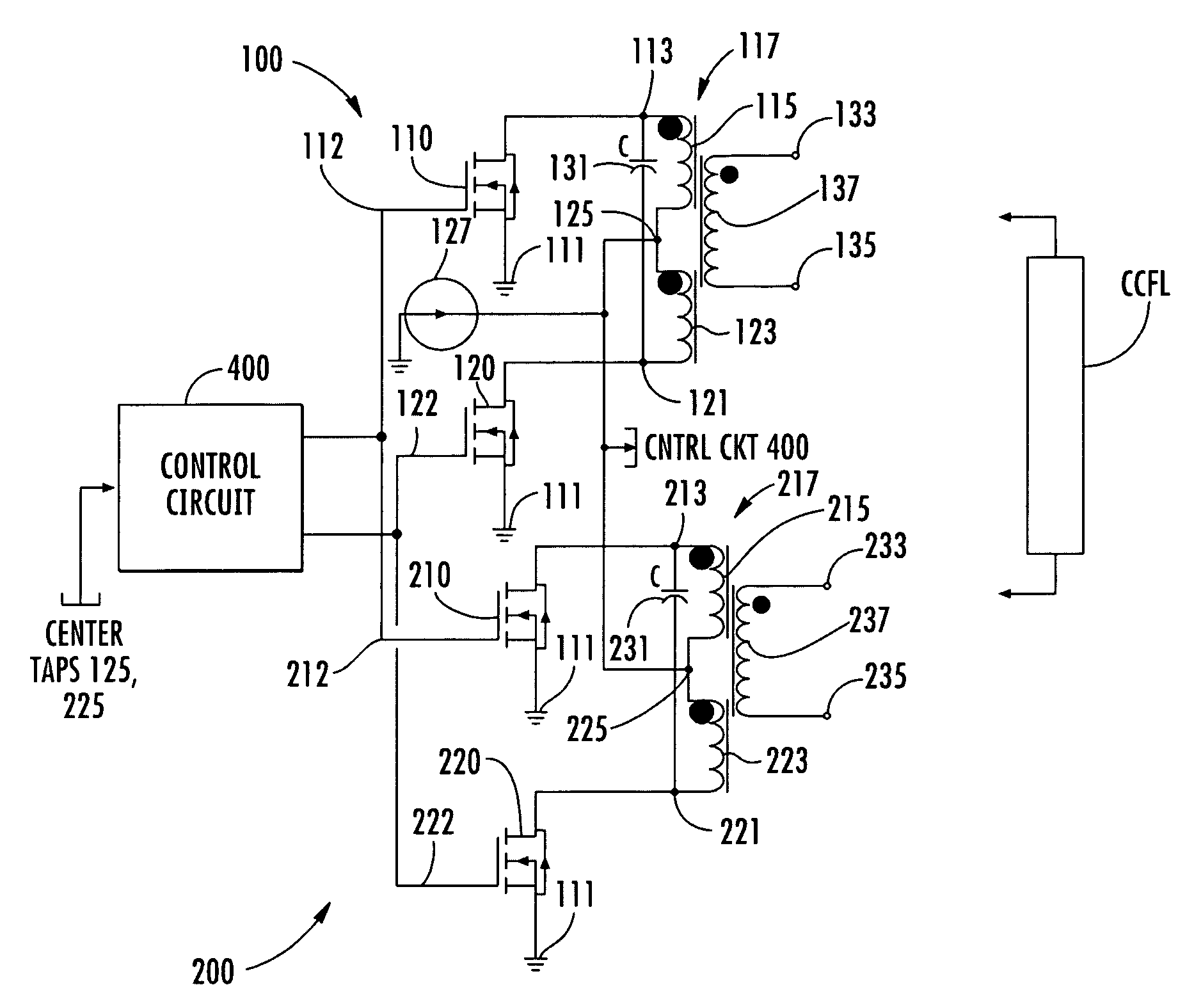
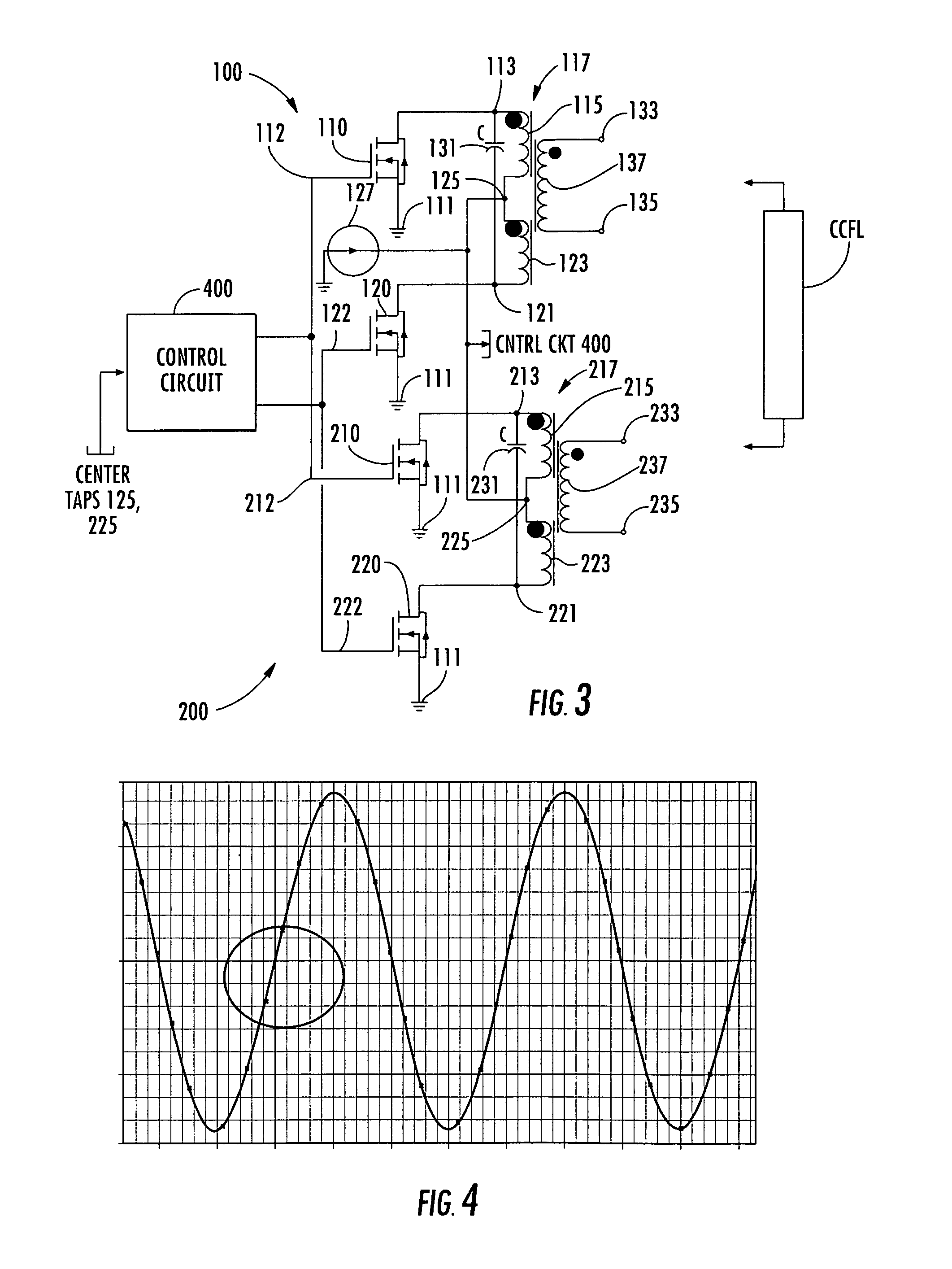
[0009]In accordance with the present invention, these and other shortcomings of conventional multi-stage, push-pull driven, resonant DC-AC converter architectures are effectively obviated by tying the center-tap points of the primary windings of the respective push-pull stages together, and driving each center-tap with a current source, rather than a voltage source. Tying the center-taps of the primary windings of the respective DC-AC converters' transformers together forces the voltages at these locations to be the same, so as to achieve mutual resonant synchronization between the two stages. Connecting the center-taps to a current source, rather than a voltage source, provides the necessary power for each stage and allows for a variation in current between stages, as the center-tap voltages track one another. In addition, the tied-together center-tap voltage is monitored to obtain the zero voltage switching required for efficient operation of the FETs of each DC-AC converter stage.

Problems solved by technology

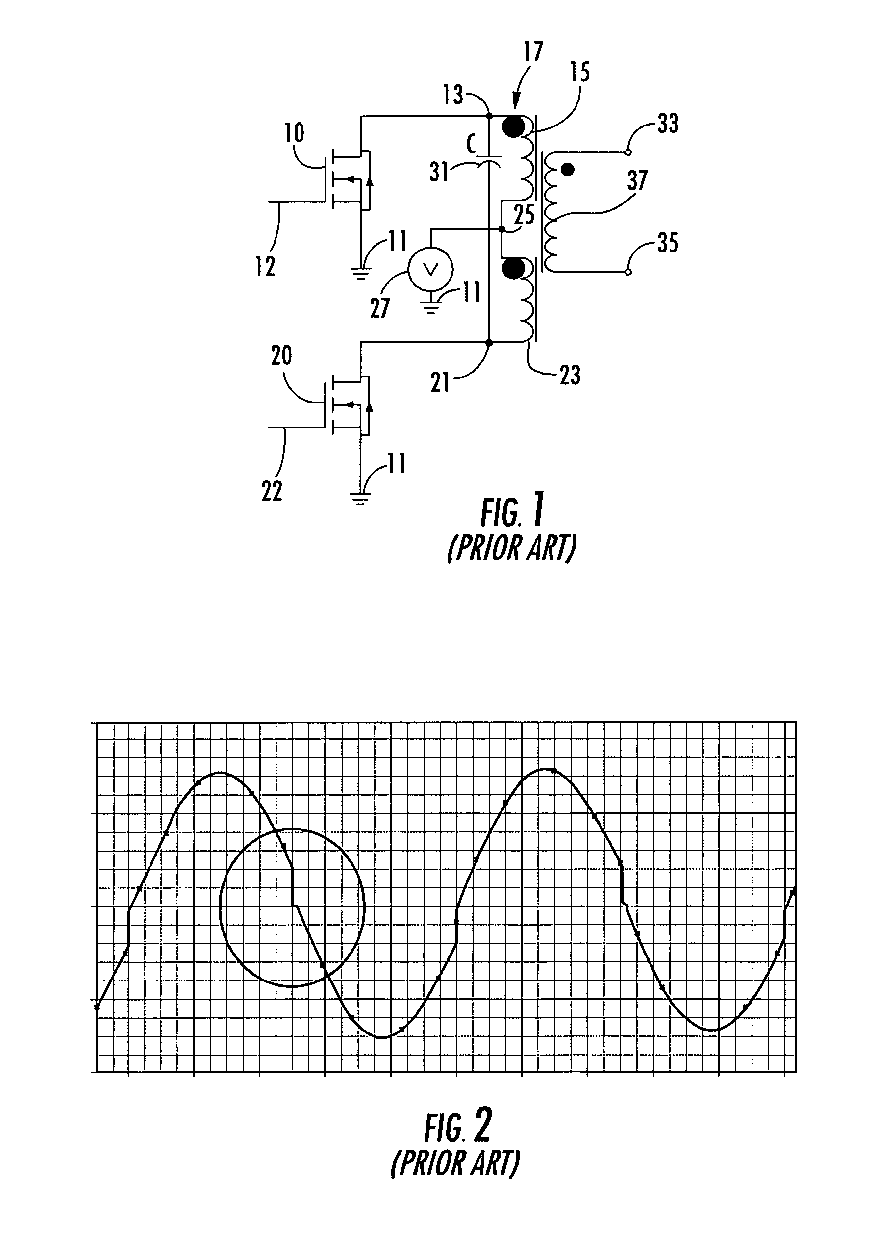
Unfortunately, the inherent differences in the parameters of each DC-AC converter's components cause the two output voltage waveforms produced thereby to have slightly different frequencies.
This leads to two problems.
First, due to variations in the components of the two tank circuits, which are not a priori known, the resonant frequencies of the two circuits are not exactly the same, resulting in the output voltage waveform containing beat frequencies, which are undesirable.
Secondly, as shown in the encircled portion of the output voltage waveform of FIG. 2, this slight difference in resonant frequencies prevents efficient zero voltage-switching of both of the push-pull switching stages that drive the tank circuits, thereby reducing the operational efficiency of one or both converters.

Method used


Image

  • Architecture for achieving resonant circuit synchronization of multiple zero voltage switched push-pull DC-AC converters
  • Architecture for achieving resonant circuit synchronization of multiple zero voltage switched push-pull DC-AC converters
  • Architecture for achieving resonant circuit synchronization of multiple zero voltage switched push-pull DC-AC converters

Examples


Embodiment Construction

[0014]Attention is now directed to FIG. 3, which is a diagrammatic illustration of a multistage, push-pull driven, resonant DC-AC converter in accordance with an embodiment of the present invention. As shown therein, the converter comprises an upper DC-AC converter stage 100 and a lower DC-AC converter stage 200. These two stages are tied together by connecting the center-taps of their respective primary transformer windings together. In particular, similar to the resonant tank-based, push-pull DC-AC converter of FIG. 1, the upper stage 100 comprises an upper controlled switching device 110, shown as an FET, which has its source-drain path coupled between a prescribed reference voltage (e.g., GND) 111, and a first end 113 of an upper coil portion 115 of a center-tapped primary winding 117 of an output transformer 119.

[0015]In a complementary manner, a lower controlled switching device 120, also shown as a field effect transistor, has its source-drain path coupled between the prescri...


PUM


Abstract

A multi-stage, push-pull driven, resonant DC-AC converter ties the center-taps of primary windings of respective push-pull stages together, and drives each center-tap with a current source. Tying the center-taps of the primary windings of the respective DC-AC converters' transformers together forces the voltages at these locations to be the same, so as to achieve mutual resonant synchronization between the two stages. Connecting the center-taps to a current source provides the necessary power for each stage and allows for a variation in current between stages, as the center-tap voltages track one another. The tied-together center-tap voltage is monitored to obtain the zero voltage switching required for efficient operation of switching devices of each DC-AC converter stage.

Description

CROSS-REFERENCE TO RELATED APPLICATION[0001]The present application claims the benefit of previously filed, co-pending U.S. Application Ser. No. 60 / 624,573, filed Nov. 3, 2004, by Z. Moussaoui et al, entitled: “Architecture for Achieving Resonant Circuit Synchronization of Multiple Zero Voltage Switched Push-Pull DC-AC Converters,” assigned to the assignee of the present application and the disclosure of which is incorporated herein.FIELD OF THE INVENTION[0002]The present invention relates in general to power supply systems and subsystems thereof, and is particularly directed to a DC-AC converter architecture that is operative to achieve resonant circuit-based synchronization of multiple DC-AC push-pull converter stages, each of which incorporates a respective LC tank circuit in its switched output supply path.BACKGROUND OF THE INVENTION[0003]FIG. 1 diagrammatically illustrates a conventional push-pull DC-AC converter which incorporates a resonant LC tank circuit in its switched out...

Claims


Application Information

Patent Timeline
Patent Type & Authority Patents(United States)
IPC IPC(8): H02M7/48H02M7/538
CPCH02M7/4826H02M7/538Y02B70/1441H02M2007/4815H02M7/4815Y02B70/10
Inventor MOUSSAOUI, ZAKIVICTORIN, THOMAS
Owner INTERSIL INC
Learn More