Micromachined magnetically balanced membrane actuator

Inactive Publication Date: 2006-05-30
SONIONMEMS
View PDF9 Cites 33 Cited by
  • Summary
  • Abstract
  • Description
  • Claims
  • Application Information

AI Technical Summary

Benefits of technology

[0028]where in the movable diaphragm shows predetermined magnetic properties, said predetermined magnetic properties varying across the substantially stiff centre part and the resilient outer part so as to avoid saturation effects of the movable diaphragm when the movable diaphragm is positioned in a magnetic flux that varies in the plane of the diaphragm.

Problems solved by technology

The fabrication is labour intensive, and thus very cost intensive.
Furthermore, the traditional loudspeaker is shock sensitive and vibrations at higher sound levels may easily cause the well-known feedback problem of hearing instruments.
The number of publications on realised loudspeakers using MST is small and none of these loudspeakers fulfils the requirements for an application in a hearing instrument.
Many publications are available on this type of micro-system actuator, but issues like low supply voltages and low power consumption have not been addressed.
A disadvantage of the actuator disclosed in U.S. Pat. No. 5,960,093 is the strong vibration resulting from the unbalanced position of the force acting point on one side of the membrane.
This requires also larger deflection of the armature in order to reach the same change in volume as a membrane deflected in a position closer to the pivot leading to a lower efficiency.
It is another disadvantage of the actuator disclosed in U.S. Pat. No. 5,690,093 that the drive pin connecting the membrane and the actuator induces additional mechanical resonances to the system thereby influencing the overall performance of the actuator.

Method used


Image

  • Micromachined magnetically balanced membrane actuator
  • Micromachined magnetically balanced membrane actuator
  • Micromachined magnetically balanced membrane actuator

Examples


Embodiment Construction

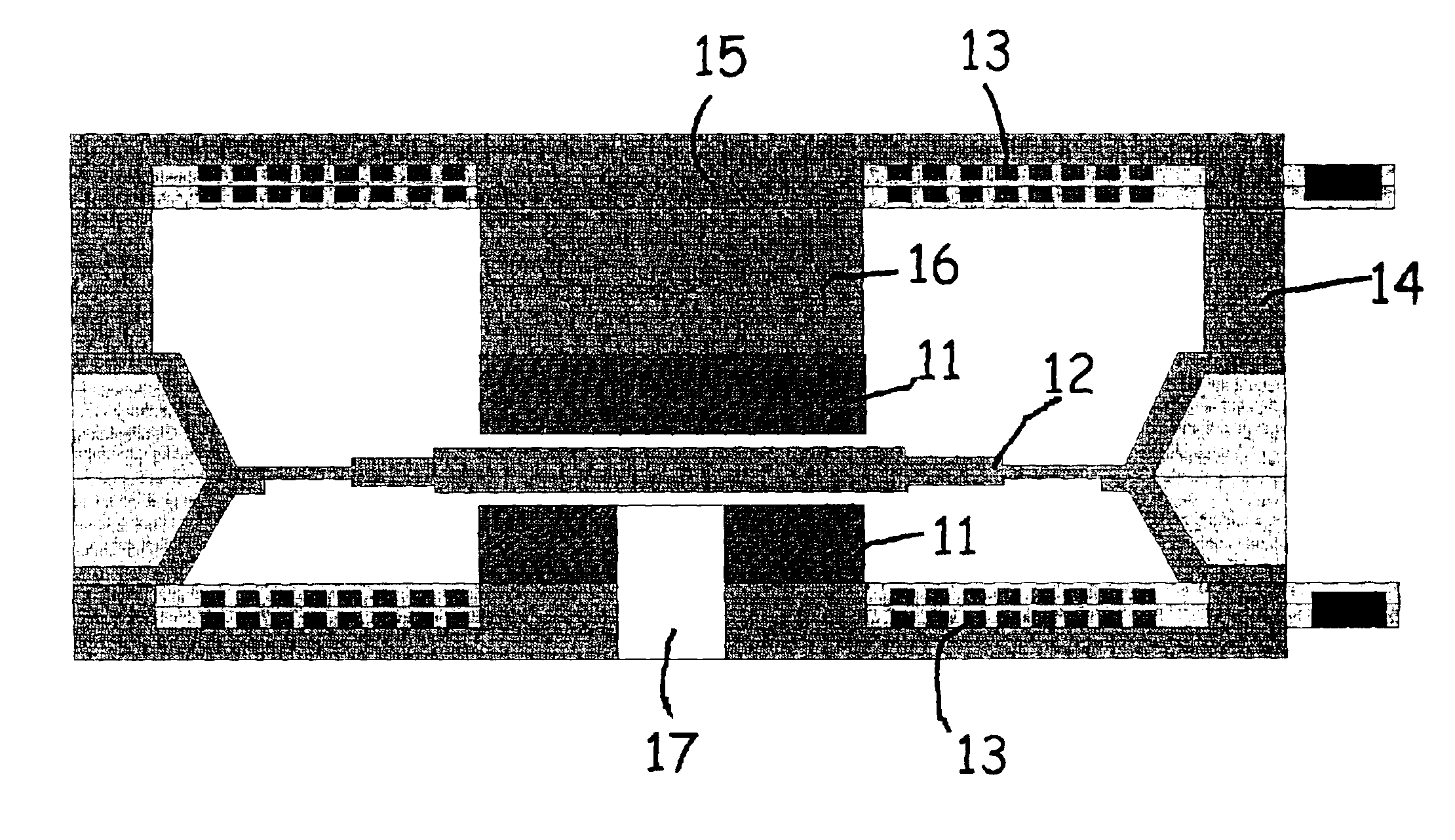
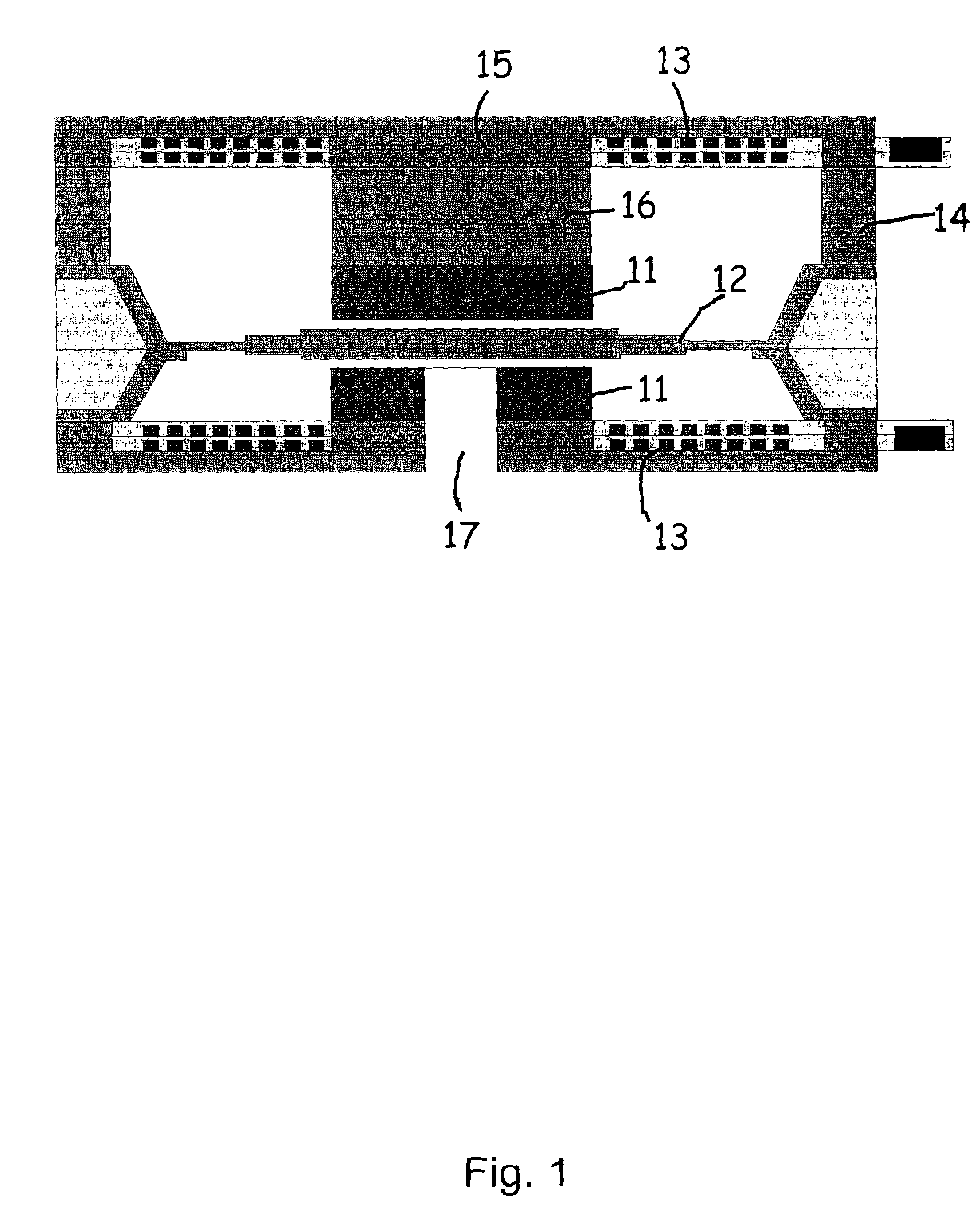
[0038]The present invention relates to an actuator operating according to the change in reluctance principle in a balanced configuration—a preferred embodiment is shown in FIG. 1—alternative embodiments are shown in FIGS. 2 and 3. This actuator - here operating as a loudspeaker—consists of two canals 10, two planar coils 13, two permanent magnets 11, a membrane 12 and a spacer chip 14 providing the necessary back chamber volume. The permanent magnets 11 have their magnetisation in the same direction producing a magnetic bias flux across the lower and upper air gap thought the core 16 and the substrate 15 and back through the side walls to the opposite side. The planar coils 13 are driven so that the produced magnetic fluxes are in opposite directions leading to a decreasing flux across one air gap and an increasing flux across the other.

[0039]The permanent magnets 11 can either be made of bulk material or by electroless—or electrochemical deposited (plated) material like Fe, Cr, Co,...


PUM


Abstract

The present invention relates to an miniature actuator especially suitable for hearing aid applications. The actuator according to the present invention operates according to the change in reluctance principle. In particular, the actuator according to the present invention operates in a balanced configuration comprising two planar coils, two magnets, a membrane and a spacer chip providing the necessary back chamber volume.

Description

[0001]This nonprovisional application claims priority under 35 U.S.C. §119(e) on U.S. Provisional Application No. 60 / 236,333 filed on Sep. 29, 2000, which is herein incorporated by reference.FIELD OF THE INVENTION[0002]The present invention relates to an actuator for hearing instruments operating according to the change in reluctance principle. In particular, the actuator according to the present invention operates in a balanced configuration comprising two planar coils, two magnets, a membrane and a spacer chip providing the necessary back chamber volume.BACKGROUND OF THE INVENTION[0003]Today, hearing instruments have dimensions which allow them to fit into the ear canal of a human being nearly invisible to the environment. Therefore, the dimensions of the components making up a hearing instrument have to decrease. This implies an enormous increase of the requirements of the traditional technology used during the last years. The fabrication is labour intensive, and thus very cost i...

Claims


Application Information

Patent Timeline
IPC IPC(8): H04R25/00
CPCH04R13/00H04R25/00
Inventor ROMBACH, PIRMINREHDER, JORG
Owner SONIONMEMS
Why Eureka
Try Eureka