Coil unit, method of manufacturing the same, and electronic instrument

a coil unit and coil technology, applied in the direction of magnets, transformers/react mounting/support/suspension, magnetic bodies, etc., can solve the problems of deteriorating mass productivity, metal sheet producing heat, and inability to reduce the thickness of the remaining portion of the coil unit to a large extent using this technology

Active Publication Date: 2008-08-21
138 EAST LCD ADVANCEMENTS LTD
View PDF8 Cites 33 Cited by
  • Summary
  • Abstract
  • Description
  • Claims
  • Application Information

AI Technical Summary

Problems solved by technology

On the other hand, the thickness of the remaining portion of the coil unit cannot be reduced to a large extent using this technology.
However, the metal sheet produces heat when applying this technology to non-contact power transmission.
Moreover, since it is necessary

Method used


Image

  • Coil unit, method of manufacturing the same, and electronic instrument
  • Coil unit, method of manufacturing the same, and electronic instrument
  • Coil unit, method of manufacturing the same, and electronic instrument

Examples


application example

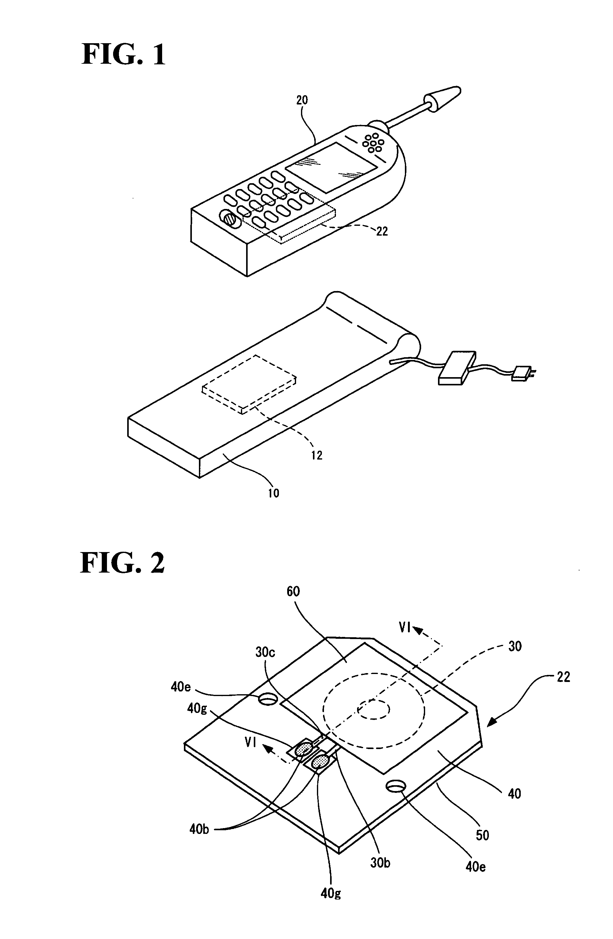
[0122](Application Example of Electronic Instrument)

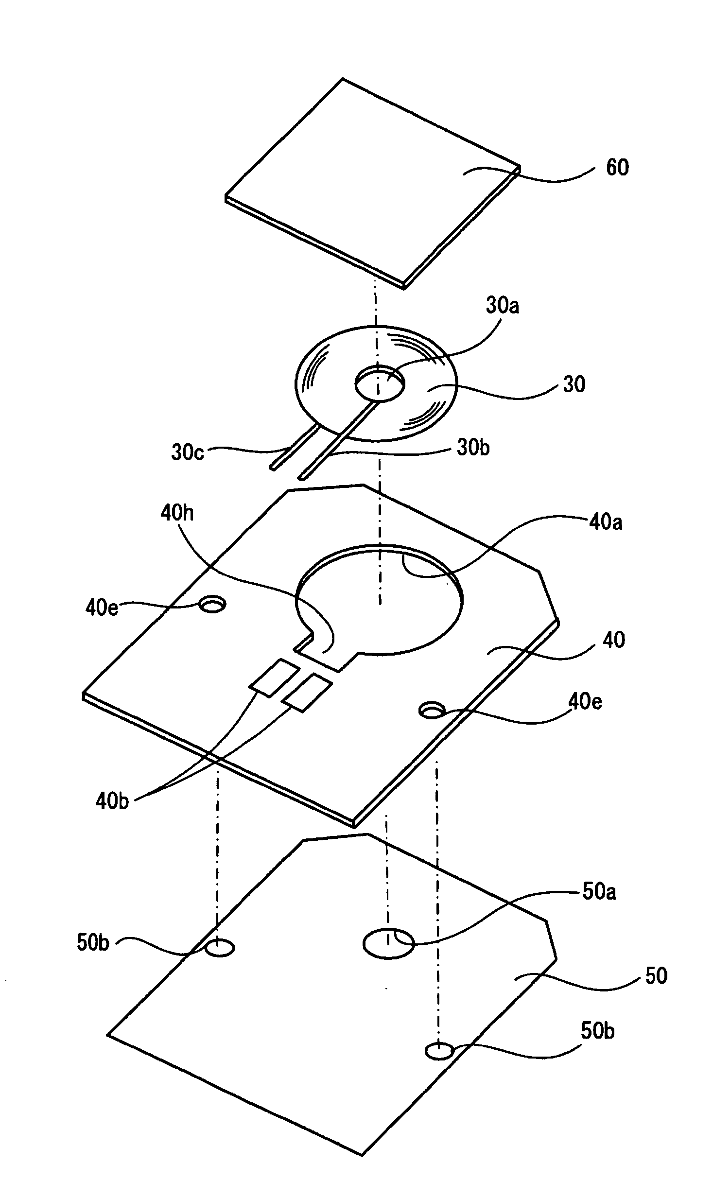
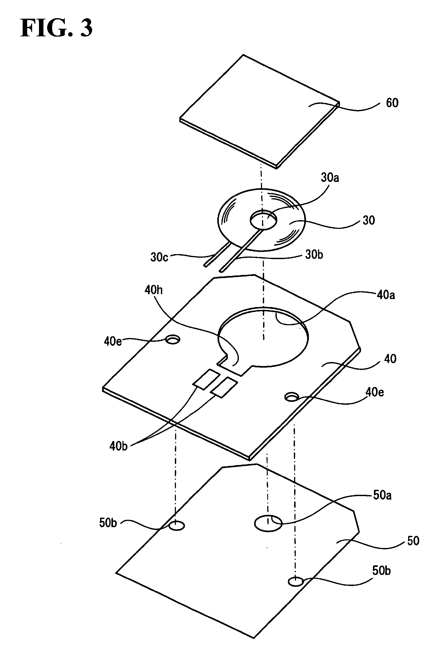
[0123]The above embodiments may be applied to an electronic instrument which performs power transmission or signal transmission. For example, the above embodiments may be applied to a charging target instrument including a secondary battery (e.g., wristwatch, electric toothbrush, electric shaver, cordless telephone, personal handyphone, mobile personal computer, personal digital assistant (PDA), or power-assisted bicycle) and a charging instrument. Since the electronic instrument according to this embodiment has a configuration in which the size of the coil unit can be easily reduced, the size of the electronic instrument can also be easily reduced. Since the planar coil is provided in the coil unit, the planar coil can be easily incorporated in the electronic instrument.

[0124]Although only some embodiments of the invention have been described in detail above, those skilled in the art would readily appreciate that many modification...


PUM

PropertyMeasurementUnit
Heightaaaaaaaaaa
Thermal conductivityaaaaaaaaaa

Abstract

A coil unit includes a planar coil, a printed circuit board that includes a planar coil placement section that receives the planar coil, a protective sheet that is provided on a transmission side of the planar coil and protects the planar coil, and a magnetic sheet that is provided on a non-transmission side of the planar coil. The planar coil is placed in the planar coil placement section and is electrically connected to the printed circuit board. The planar coil placement section has a shape that corresponds to an external shape of the planar coil.

Description

[0001]Japanese Patent Application No. 2007-39887 filed on Feb. 20, 2007, is hereby incorporated by reference in its entirety.BACKGROUND OF THE INVENTION[0002]The present invention relates to a coil unit relating to non-contact power transmission using a coil, a method of manufacturing the same, an electronic instrument, and the like.[0003]Non-contact power transmission has been known which enables power transmission without metal-to-metal contact utilizing electromagnetic induction. As application examples of non-contact power transmission, charging a portable telephone, a household appliance (e.g., telephone handset), and the like has been proposed.[0004]In recent years, a reduction in size of portable telephones has been increasingly desired. This makes it necessary to reduce the size (particularly thickness) of a power transmission coil unit. JP-A-8-148360, JP-A-2005-26743, and JP-A-2005-260122 disclose technologies relating to a reduction in size of a coil unit.[0005]JP-A-8-1483...

Claims


Application Information

Patent Timeline
IPC IPC(8): H01F27/30H05K3/32H01F27/02H01F27/06H01F27/28H01F27/29H01F27/32H01F27/36H01F38/14H01F41/04
CPCH01F27/22H01F27/2871H01F27/292H01F27/306H01F38/14Y10T29/49078H05K1/182H05K2201/086H05K2201/1003H05K2201/10462H05K2203/1311H01F41/04
Inventor HASEGAWA, MINORUKURODA, MASAO
Owner 138 EAST LCD ADVANCEMENTS LTD
Why Eureka
Try Eureka