
Method and apparatus for storage device performance measurement

a technology for storage devices and performance measurement, applied in the direction of maintaining head carrier alignment, instruments, nuclear elements, etc., can solve the problems of time-consuming and expensive, error correction delay, and inability to ensure that the amount of buffer memory will be sufficient for other data transfer rates

Inactive Publication Date: 2006-05-30
MAXTOR
View PDF6 Cites 75 Cited by
  • Summary
  • Abstract
  • Description
  • Claims
  • Application Information

AI Technical Summary

Benefits of technology

"The present invention provides a method for measuring the performance of a storage device that uses rotatable media to store and retrieve data. The method involves specifying access patterns for transferring data to and from the media, and for each access pattern, specifying the required data transfer rate. The actual data transfer time is measured for each access pattern and the performance of the storage device is determined based on the actual data transfer time and the required data transfer rate. The method also includes adjusting the virtual buffer size for each data transfer rate and selecting a buffer based on the adjusted virtual buffer size to allow streaming data to and from the storage device at the required data transfer rate. The software and apparatus for implementing this method are also provided."

Problems solved by technology

The unique requirements of such applications, relative to typical disk drive applications in personal computer environments, for example, are that data streaming applications require not only data integrity, but also substantially fixed storage and retrieval data transfer rates that are not flexible.
This is due to varying data transfer rates across disk diameters, the requirement to interrupt data streams in order to change location (seek), and the possibility of error correction delays.
Determining the amount of buffer memory required, by measuring disk drive performance for a worst case streaming data transfer rate requirement, does not ensure that the amount of buffer memory will be sufficient for other data transfer rate requirements.
This is very time consuming and expensive, substantially decreasing productivity, and increasing disk drive costs for the manufacturers and consumers.

Method used


Image

  • Method and apparatus for storage device performance measurement
  • Method and apparatus for storage device performance measurement
  • Method and apparatus for storage device performance measurement

Examples


Embodiment Construction

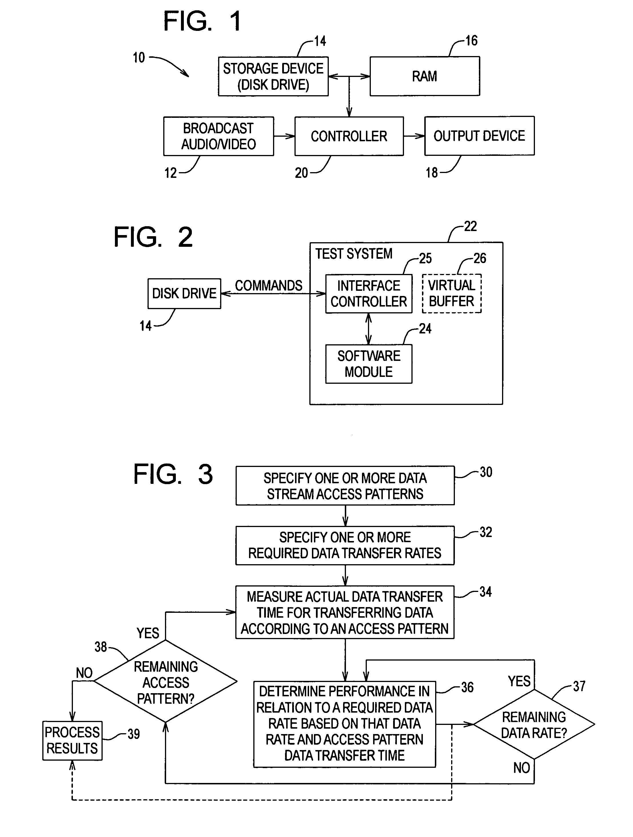
[0021]FIG. 1 shows an example architectural block diagram of an embodiment of an A / V system 10 including a storage device 14 such as a disk drive. The A / V system 10 utilizes the hard-disk drive 14 to deliver information to a host application in a timely fashion according to a strict data streaming schedule (e.g., data transfer rate). Such a host application is referred to herein as ‘data streaming’ application. The unique requirements of such host applications relative to typical hard drive applications (e.g., in personal computer environments) are that data streaming in such host applications emphasize not only data integrity, but also storage and retrieval data transfer rates that are not flexible.

[0022]The example A / V system 10 includes a broadcast source 12 for originating analog or digital audio / video data, a storage device 14 such as a disk drive for storing the data, a memory (e.g., RAM) 16 for buffering data, an output device 18 such as a display device (e.g., TV, monitor, H...


PUM


Abstract

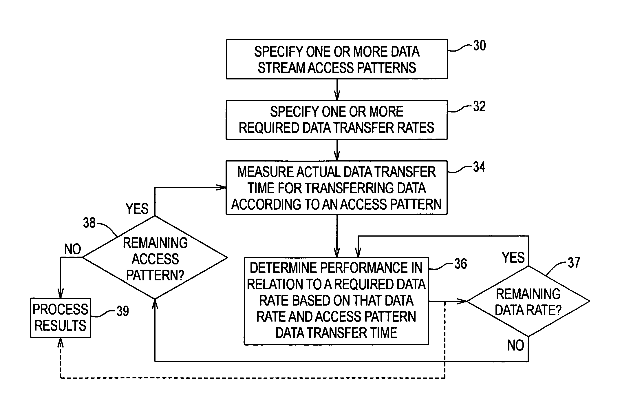
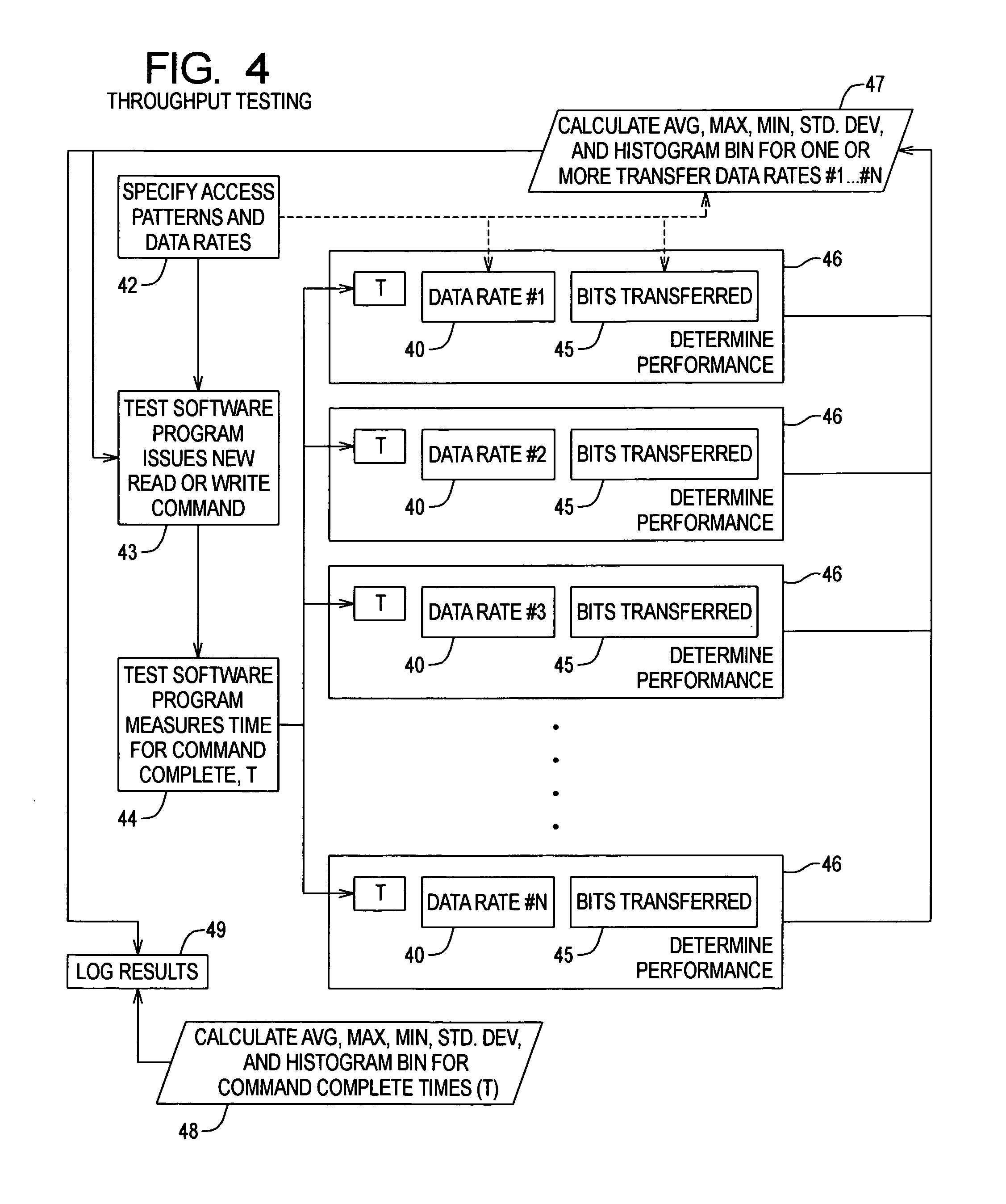
Method for measuring performance of a storage device including rotatable media, for storing data to and / or retrieving data from said media via one or more data buffers. The measurement method includes the steps of: specifying one or more access patterns for transferring data to / from the media; and for each access pattern, specifying one or more different required data transfer rates, measuring the actual data transfer time of the storage device for transferring the data according to that access pattern, and determining performance of the storage device in relation to each required data transfer rate based on the actual data transfer time for the data.

Description

FIELD OF THE INVENTION[0001]The present invention relates to measuring performance of storage devices for storing and retrieving information, and more particularly, to measuring performance of storage devices for storing and retrieving audio / video information.BACKGROUND OF THE INVENTION[0002]Storage devices utilizing rotating media, such as hard disk drives, are increasingly utilized for storage / retrieval of audio / video (A / V) information. A requirement for such disk drives is to deliver information to host applications, such as data streaming applications, in a timely fashion according to a strict data delivery schedule. The unique requirements of such applications, relative to typical disk drive applications in personal computer environments, for example, are that data streaming applications require not only data integrity, but also substantially fixed storage and retrieval data transfer rates that are not flexible. For example, personal video recorders or digital video recorders, ...

Claims


Application Information

Patent Timeline
Patent Type & Authority Patents(United States)
IPC IPC(8): G06F11/30
CPCG06F11/3419G06F11/3414Y10S707/99936G06F2201/815G06F11/3452
Inventor RICH, PHIL
Owner MAXTOR
Learn More