
Electro pneumatic hybrid brake control method and system based on network data transfer mode

A network data transmission and control method technology, applied in the electro-pneumatic hybrid brake control method and system field, can solve the problems of air brake overshoot idling distance, impact on precise parking, impact, etc., to reduce redundant investment and reduce redundant Delay effect

Active Publication Date: 2013-10-23
ZHUZHOU CSR TIMES ELECTRIC CO LTD
View PDF6 Cites 33 Cited by
  • Summary
  • Abstract
  • Description
  • Claims
  • Application Information

AI Technical Summary

Problems solved by technology

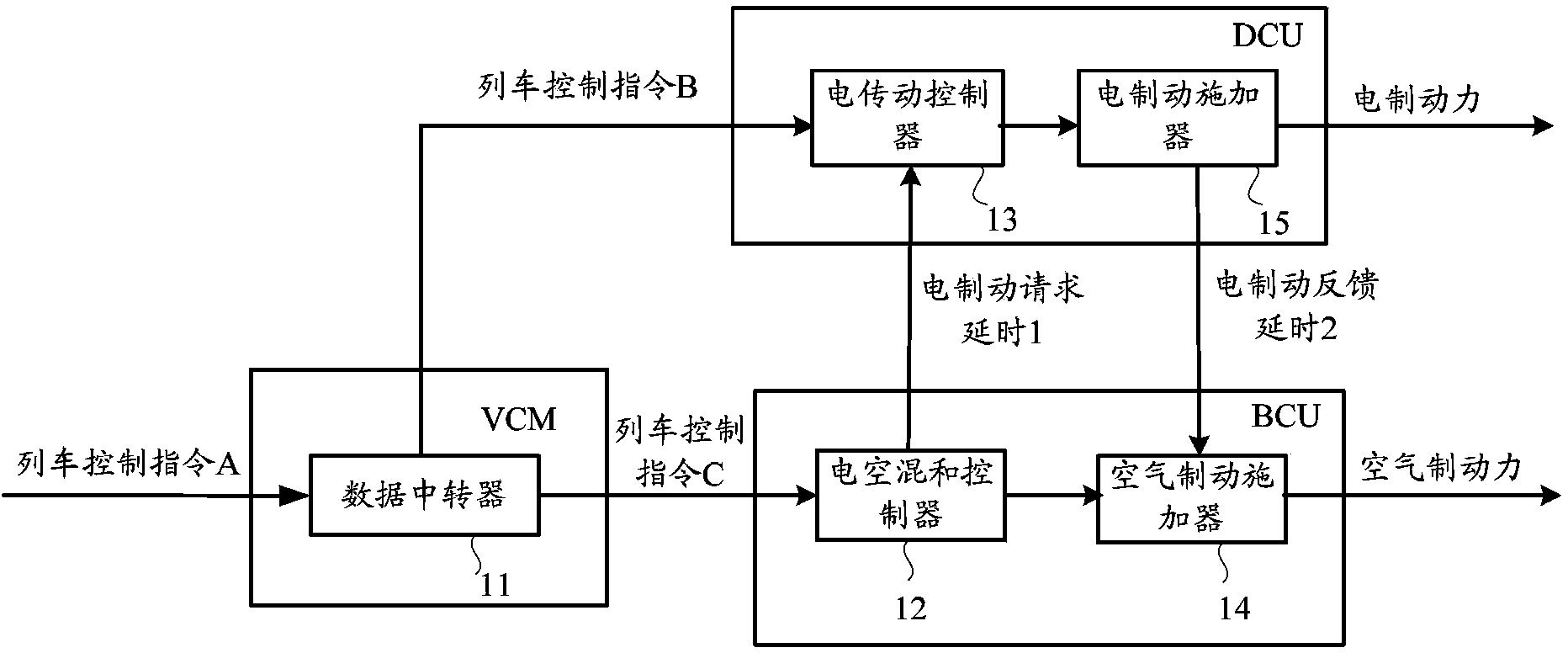
[0007] a) During the initial rising phase of the braking force, due to the existence of the traction force fading time and the data transmission delay between the DCU and the BCU, redundant air brake overshoot or too long idling distance often occur. The adjustment of the setting can not completely solve this contradiction
[0008] b) In the process of changing the braking level, due to the untimely feedback of the electric braking force, additional air braking often occurs, and often superimposed with the electric braking, resulting in fluctuations and impacts of train braking
[0009] c) During the transition from parking electric braking to air braking, due to the delay of electric braking force application and electric braking force feedback, it will also cause the superimposed total braking force of air braking force application and electric braking force application in the conversion stage Unable to respond smoothly to the braking command, resulting in constant adjustment of the braking command, which makes the calculation of the braking distance inaccurate and affects precise parking

Method used


Image

  • Electro pneumatic hybrid brake control method and system based on network data transfer mode
  • Electro pneumatic hybrid brake control method and system based on network data transfer mode
  • Electro pneumatic hybrid brake control method and system based on network data transfer mode

Examples


Embodiment Construction

[0037] In order to make the object, technical solution and advantages of the present invention clearer, the present invention will be further described in detail below in conjunction with the accompanying drawings.

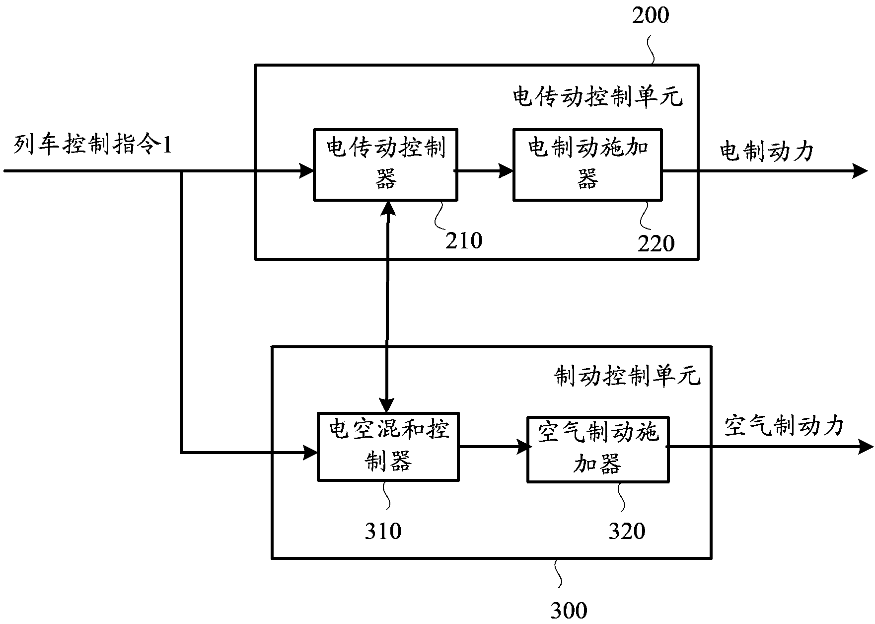
[0038] see figure 2 , figure 2 It is a structural diagram of an electro-pneumatic hybrid braking control system based on network data transmission according to an embodiment of the present invention.

[0039] The control system includes an electric transmission control unit 200 and a brake control unit 300 . Further, the electric transmission control unit 200 includes an electric transmission controller 210 and an electric brake applicator 220 coupled thereto. The brake control unit 300 includes an electropneumatic hybrid controller 310 and an air brake applicator 320 coupled thereto. It should be noted that, in this embodiment, the data transmitted between the electro-pneumatic hybrid controller 310 and the electric transmission controller 210, in addition to ...


PUM


Abstract

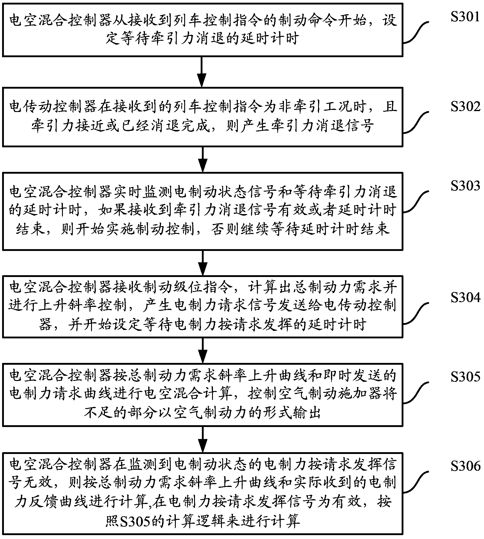
The invention discloses an electro pneumatic hybrid brake control method and system based on a network data transfer mode. The method comprises the following steps: a first setting step, namely setting time delay timing for waiting the subsidence of tractive force so long as a brake command of a train control command is received by a brake control unit; a first monitoring step, namely using the brake control unit to monitor an electrical braking state signal and the time delay timing for waiting the subsidence of tractive force from an electric transmission control unit, and conducting brake control if the electrical braking state signal represents effective tractive force subsidence signal or the time delay timing is stopped, otherwise waiting the stop of the time delay timing. According to the invention, the signals can be input by adding the tractive force subsidence signal or electrical braking, data transmission time delay generated in the initial rising process of brake force in the prior art can be eliminated.

Description

technical field [0001] The invention relates to the technical field of locomotives and trains, in particular to an electro-pneumatic hybrid braking control method and system based on a network data transmission mode. Background technique [0002] In the control of fixed marshalling trains, compared with the network data transmission mode, the hard-wire data transmission mode has the disadvantages of low fault tolerance rate and large wiring resource occupation. With the improvement of train network technology, the reliability of network data transmission has been greatly improved, making it a trend to remove data transmission hard lines that are not safe. But at the same time, the relatively large delay of the network data transmission mode also affects the mutual cooperation of the various control units of the train. This effect is especially reflected in the hybrid control of electric braking and air braking. [0003] Train braking control has requirements such as electri...

Claims


Application Information

Patent Timeline
Patent Type & Authority Applications(China)
IPC IPC(8): B61H11/06B60L7/00
Inventor 余接任谭寿云钱华毛康鑫肖华
Owner ZHUZHOU CSR TIMES ELECTRIC CO LTD
Learn More