Apparatus and method for branch prediction where data for predictions is selected from a count in a branch history table or a bias in a branch target buffer

a branch history and data selection technology, applied in the field of branch history table data selection and branch target buffer bias, can solve the problems of pipeline operation disturbance, degrading prediction accuracy, interference between records, etc., to avoid pipeline operation disturbance, avoid interference of pht entries, and highly accurate branch predictions

Inactive Publication Date: 2006-05-30
FUJITSU LTD
View PDF17 Cites 25 Cited by
  • Summary
  • Abstract
  • Description
  • Claims
  • Application Information

AI Technical Summary

Benefits of technology

[0021]In the apparatus as described above, the provision of a portion of an instruction as a tag in the history table (PHT) makes it possible to avoid interference of PHT entries between different branch instructions. When a tag does not match a current instruction upon reference to the first index, this means that information about the current instruction under the current history condition is not registered. In this case, the branch destination buffer (BTB) is used for branch prediction. Namely, the first value of the history table is used for branch prediction if the hist

Problems solved by technology

In processors based on pipeline operations, waiting for branch results to be known before jumping to branch addresses results in the delay of instruction fetch timing, causing disturbance in the pipeline operation.
Further, branch directions may often have globally lopsided tendency in branch directions such that a given branch instruction is likely to branch or is not likely to branch depending on the branching results of recently executed branch instructions.
If more than one branch instruction is present in a program, however, the outcomes of different branch instructions interfere with each other in the PHT u

Method used


Image

  • Apparatus and method for branch prediction where data for predictions is selected from a count in a branch history table or a bias in a branch target buffer
  • Apparatus and method for branch prediction where data for predictions is selected from a count in a branch history table or a bias in a branch target buffer
  • Apparatus and method for branch prediction where data for predictions is selected from a count in a branch history table or a bias in a branch target buffer

Examples


Embodiment Construction

[0030]In the following, embodiments of the present invention will be described with reference to the accompanying drawings.

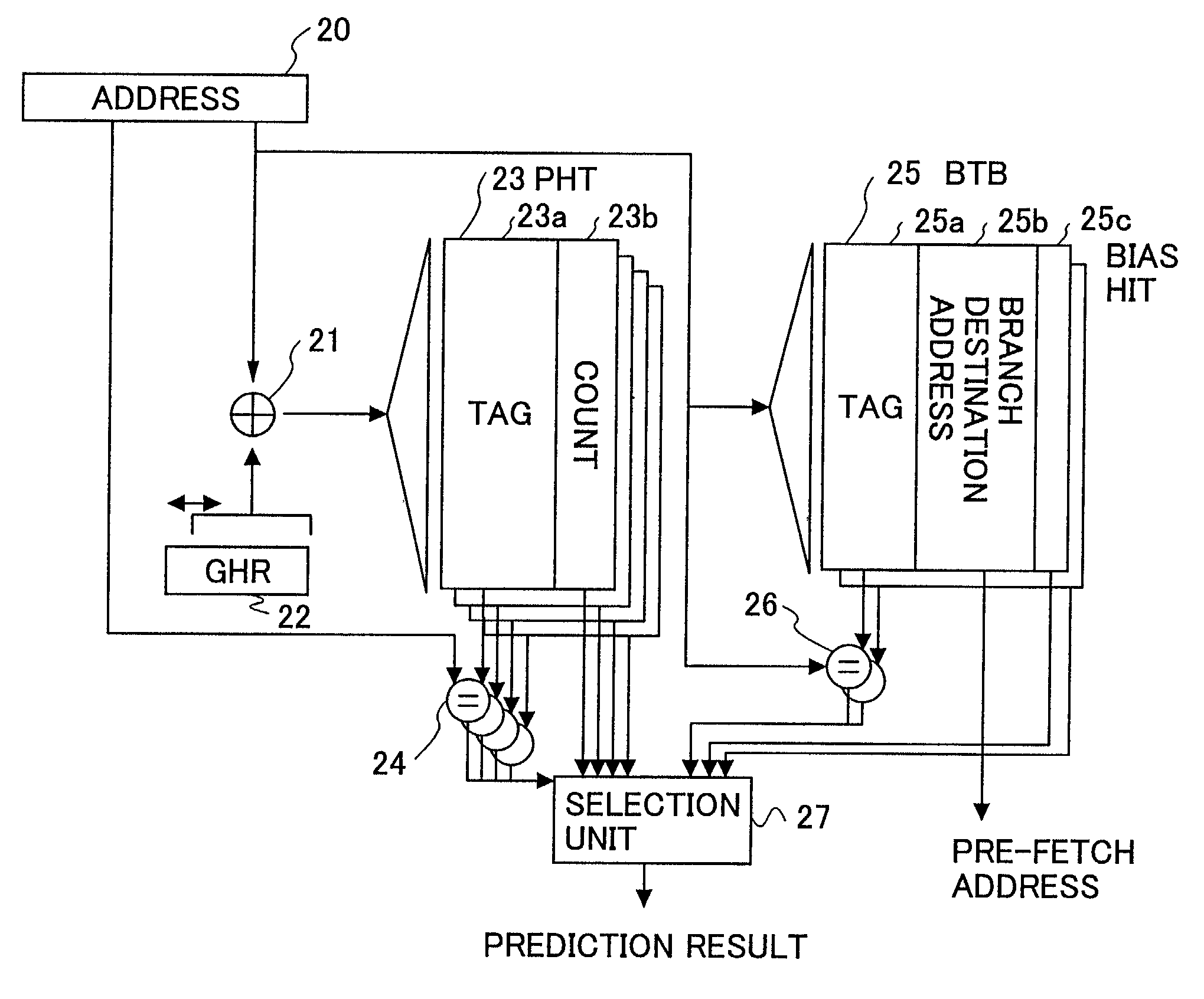
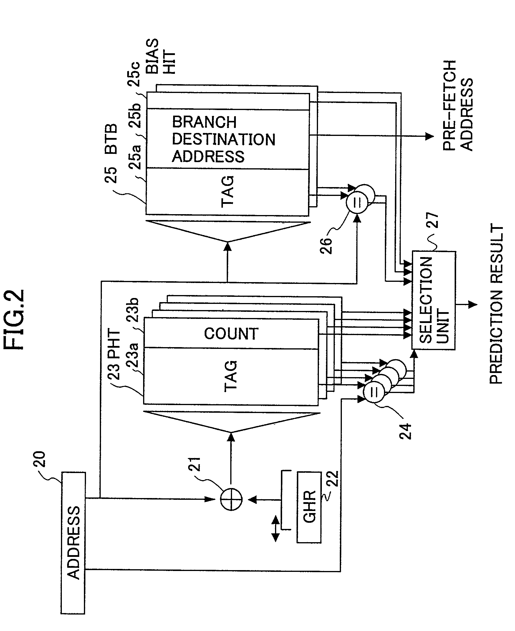
[0031]FIG. 2 is a block diagram of a branch prediction apparatus based on the use of a PHT according to the present invention.

[0032]The branch prediction apparatus according to the present invention includes an XOR circuit 21, a GHR unit 22, a tag-attached PHT unit 23, a comparison unit 24, a BTB (branch target buffer) 25, a comparison unit 26, and a selection unit 27.

[0033]The GHR (global history register) unit 22 is a register that stores therein the history of recently executed branch instructions as to whether or not they branched. When a given branch instruction branches, the contents of the register is shifted one bit to the left, with “1” being inserted into the least significant bit. When a given branch instruction does not branch, the contents of the register is shifted one bit to the left, with “0” being inserted into the least significant bit. The XOR...


PUM


Abstract

An apparatus for branch prediction includes a history register which stores therein history of previous branch instructions, an index generation circuit which generates a first index from an instruction address and the history stored in the history register, a history table which stores therein a portion of the instruction address as a tag and a first value indicative of likelihood of branching in association with the first index, a branch destination buffer which stores therein a branch destination address or predicted branch destination address of an instruction indicated by the instruction address and a second value indicative of likelihood of branching in association with a second index that is at least a portion of the instruction address, and a selection unit which makes a branch prediction by selecting one of the first value and the second value.

Description

BACKGROUND OF THE INVENTION[0001]1. Field of the Invention[0002]The present invention generally relates to methods of predicting branching of branch instructions and processors employing such methods, and particularly relates to a method of predicting branching of branch instructions based on PHT (pattern history table) and a processor employing such a method.[0003]2. Description of the Related Art[0004]In processors based on pipeline operations, waiting for branch results to be known before jumping to branch addresses results in the delay of instruction fetch timing, causing disturbance in the pipeline operation. It is thus necessary to predict branching before actually executing branch instructions, thereby making it possible to fetch instructions in a continuous stream in accordance with the pipeline operations.[0005]Branch instructions often have locally lopsided tendency in branch directions such that a given branch direction, of itself, is likely to branch or is not likely to ...

Claims


Application Information

Patent Timeline
IPC IPC(8): G06F9/32G06F9/38
CPCG06F9/3848G06F9/3806
Inventor TAGO, SHINICHIROYAMANA, TOMOHIROTAKEBE, YOSHIMASA
Owner FUJITSU LTD
Why Eureka
Try Eureka