Closet flange with knockout retainer

a technology of retainer and flange, which is applied in the field of flanges, can solve the problems of large blockage, debris naturally falling into the drain pipe, and the drain pipe remains unsealed,

Active Publication Date: 2006-06-06
IPS
View PDF32 Cites 34 Cited by
  • Summary
  • Abstract
  • Description
  • Claims
  • Application Information

AI Technical Summary

Benefits of technology

[0008]According to the present invention, a closet flange is provided for coupling the base of a toilet to a drain pipe. A main generally cylindrical body portion is dimensioned for connection to the upper end of a drain pipe and has a through bore for communicating with the interior of the drain pipe. An attachment flange portion extends radially outward from an upper end of the cylindrical body portion and is configured for connecting to the base of a toilet. A knockout temporarily seals the through bore and is removable by breaking away a peripheral edge of the knockout. A retainer extends radially inward from an inner wall of the cylindrical portion below the knockout and is configured to prevent the knockout from falling down the through bore when broken away.

Problems solved by technology

A problem continually faced by plumbers involves the prevention of clogging of toilet drain pipes during construction owing to the fact that these pipes are usually installed long before the toilet is mounted over the same.
Sawdust, nails, wood chips, putty, screws, tape, paper, and even blocks of wood fall into the open upper ends of the drain pipes and cause major blockages after the newly completed building is occupied.
However, since most plumbing codes require pressure testing of the drain system to detect leaks, it is necessary to provide an air tight seal.
Mechanical and pneumatic test plugs have been used with some success, but when the test is completed the drain pipe remains unsealed.
Since the upper end of the pipe is at floor level, debris naturally falls into the drain pipe.
Gluing on a pressure test cap is time consuming and its removal is difficult.
This requires pipe threads to provide an airtight seal, and such threads are not practical to form during injection molding of a single unitary closet flange.
U.S. Pat. No. 4,827,539 of Kiziah discloses a closet flange with an integral knockout plug 10′ which can fall well down into the drain pipe during attempted removal of the plug making it extremely difficult to retrieve

Method used


Image

  • Closet flange with knockout retainer
  • Closet flange with knockout retainer
  • Closet flange with knockout retainer

Examples


Embodiment Construction

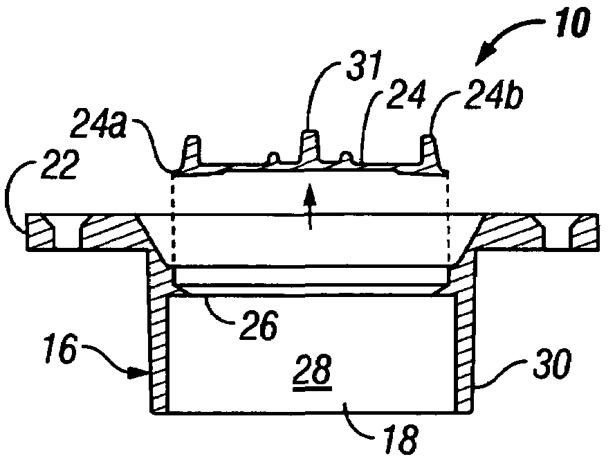
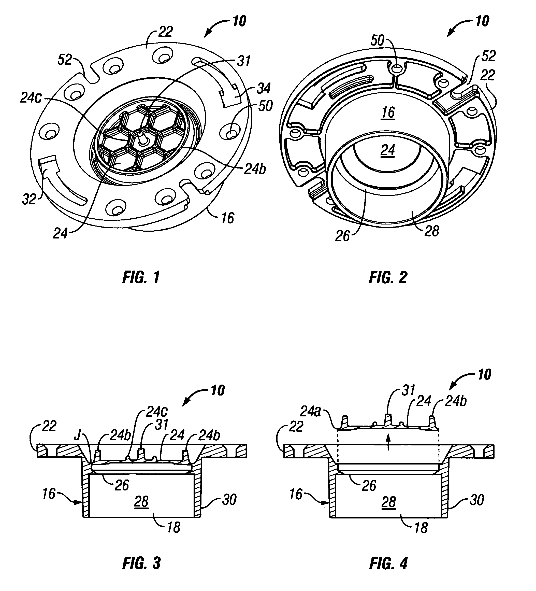
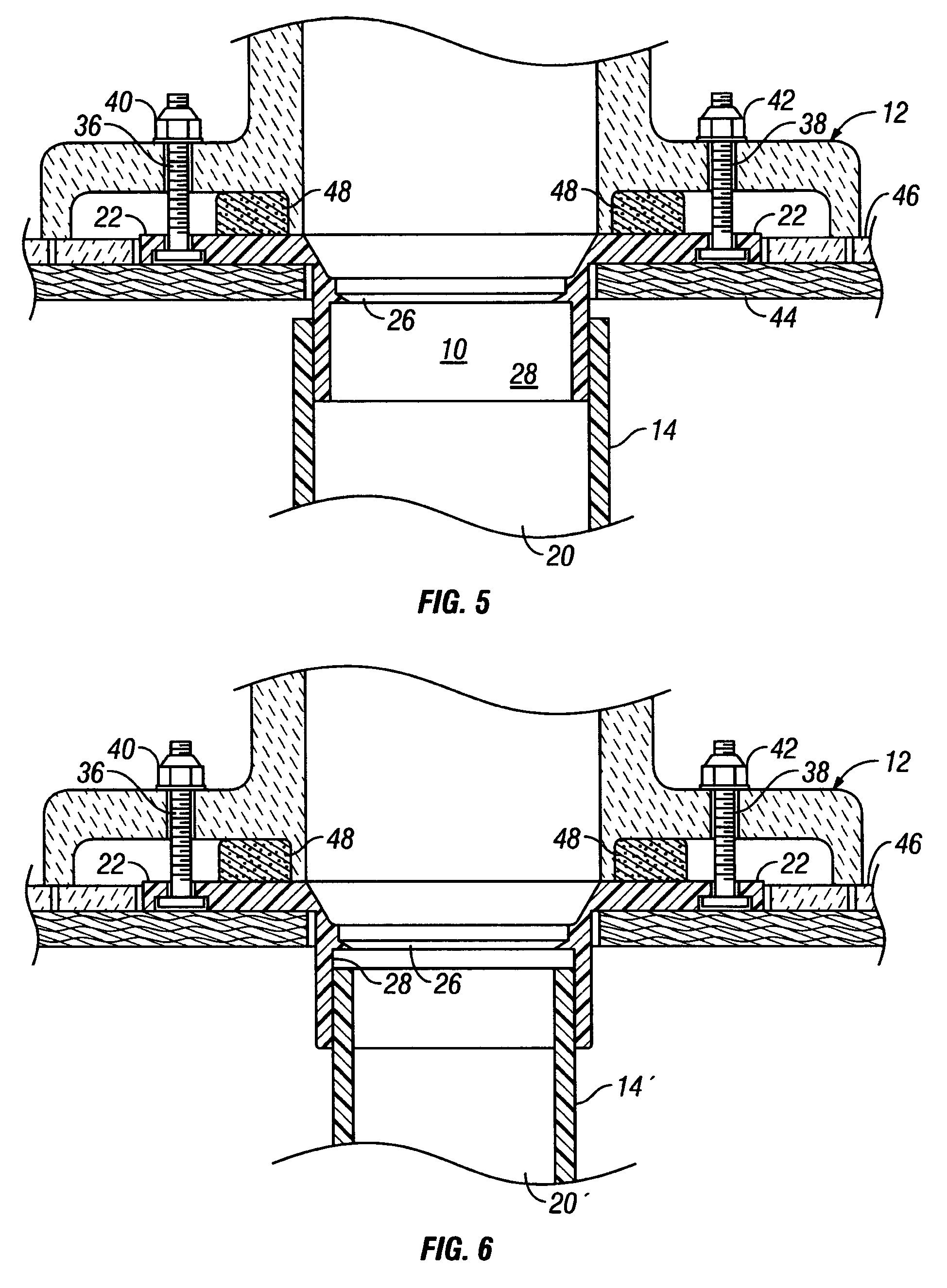
[0015]Referring to FIG. 5, a plastic closet flange 10 is provided for coupling the base of a conventional porcelain toilet 12 to a plastic drain pipe 14. A main generally cylindrical body portion 16 (FIG. 2) is dimensioned for connection to the upper end of the drain pipe 14 and has a through bore 18 (FIG. 3) for communicating with the interior 20 (FIG. 5) of the drain pipe 14. An annular attachment flange portion 22 (FIG. 1) extends radially outward from an upper end of the cylindrical body portion 16 and is configured for connecting to the flat underside of the base of the toilet 12. A generally disc-shaped knockout 24 temporarily seals the through bore 18 and is removable by breaking away a peripheral edge 24a (FIG. 4) of the knockout 24. A retainer 26 (FIGS. 2 and 3) extends radially inward from an inner wall 28 of the cylindrical portion 16 below the knockout 24 and is configured to prevent the knockout 24 from falling down the through bore 18 and down the interior 20 of the dr...


PUM


Abstract

A closet flange is provided for coupling the base of a toilet to a drain pipe. A main generally cylindrical body portion is dimensioned for connection to the upper end of a drain pipe and has a through bore for communicating with the interior of the drain pipe. An attachment flange portion extends radially outward from an upper end of the cylindrical body portion and is configured for connecting to the base of a toilet. A knockout temporarily seals the through bore and is removable by breaking away a peripheral edge of the knockout. A retainer extends radially inward from an inner wall of the cylindrical portion below the knockout and is configured to prevent the knockout from falling down the through bore and into the drain pipe when broken away in order to prevent drain clogging.

Description

FIELD OF THE INVENTION[0001]The present invention relates to plumbing parts and more particularly to flanges for connecting a toilet to a drain pipe.BACKGROUND OF THE INVENTION[0002]In residential and commercial building construction it is necessary to connect the base of a porcelain toilet to a drain pipe in a secure and water tight manner that meets all plumbing codes applicable in the local jurisdiction. The most common way of achieving this connection is to utilize a so-called closet flange. See for example U.S. Pat. Nos. 3,181,585; 3,339,215; and 4,090,267. The typical closet flange is flat and round and includes a pair of semi-circular diametrically opposed key-shaped slots which allow for the insertion of bolts that are used to tighten the base of the toilet to the flange. Early closet flanges were made of cast iron and were connected to cast iron drain pipes. Modem closet flanges are typically made of ABS or PVC plastic and include a main cylindrical body portion that is sol...

Claims


Application Information

Patent Timeline
Patent Type & Authority Patents(United States)
IPC IPC(8): E03D11/16E03D11/00
CPCE03D11/16
Inventor HUMBER, JEFFREY A.
Owner IPS
Why Eureka
Try Eureka