Patient bed with CPR system

a patient bed and cpr technology, applied in the field of patient beds, can solve the problems of significant limitations in the design of beds, physical limitations of the bed operator, and the use of electrical components in patient beds

Active Publication Date: 2006-06-06
STRYKER CORP
View PDF19 Cites 118 Cited by
  • Summary
  • Abstract
  • Description
  • Claims
  • Application Information

AI Technical Summary

Benefits of technology

[0018]According to an aspect of the present invention, there is provided an emergency system for a patient bed comprising: an electrically powered linear actuator operable to drive a back rest of the patient bed from a lowered back rest position to a raised back rest position, and operable to permit the back rest to lower from the raised back rest position to the lowered back rest position without being driven by the linear actuator; and, an independent electrical activation means for activating the linear actuator to permit the back rest to lower from the raised back rest position to the lowered back rest position without being driven by the linear actuator, the electrical activation means not requiring continued operator attendance for continued lowering of the back rest.
[0019]According to another aspect of the present invention, there is provided a patient bed comprising a patient support platform having a back rest portion; an electrically powered linear actuator operable to drive the back rest from a lowered back rest position to a raised back rest position, characterized in that the linear actuator is operable to permit the back rest to lower from the raised back rest position to the lowered back rest position without being driven by the linear actuator; and, the bed further comprises an emergency back rest lowering system comprising an independent electrical activation means for activating the linear actuator to permit the back rest to lower from the raised back rest position to the lowered back rest position without being driven by the linear actuator, the electrical activation means not requiring continued operator attendance for continued lowering of the back rest.
[0027]It is an important aspect of the emergency system of the present invention that the electrical activation means does not require continued operator attendance for continued functioning. As stated above, the standard for electrically powered beds requires that electrically powered functional movements of the bed be possible only by means of momentary contact switches that stop the movement when the switch is released. Therefore, it is surprising to one skilled in the art that an electrically activated emergency system, such as the emergency system provided by the present invention, can work without momentary contact switches that stop the linear actuators when the switch is released.
[0029]Limit switches may also be used to cut power to electrically activated components of the emergency system and / or other electrically operated parts of the bed. In such instances, movement of a moving part beyond a pre-selected point would trip a limit switch to cut electrical power to the moving part. Limit switches are generally used as an added safety measure, to reduce power consumption, etc.

Problems solved by technology

Consequently, physical limitations of the bed's operator represent significant limitations to the design of beds where position changes are accomplished solely by mechanical means.
Where access to the switches by the patient is undesirable, the control panel may be located in an area of the bed that is normally inaccessible to the patient in the bed, for example, on the outside face of the foot board.
Despite the flexibility offered by the use of electrical components, there remains limitations, often driven by regulatory considerations, to the use of electrical components in patient beds.
Since momentary contact switches turn off the functioning of a moving part when the switch is released, electrical activation of an emergency system on a patient bed has been heretofore considered impossible within the context of the above-noted standards.

Method used


Image

  • Patient bed with CPR system
  • Patient bed with CPR system
  • Patient bed with CPR system

Examples


Embodiment Construction

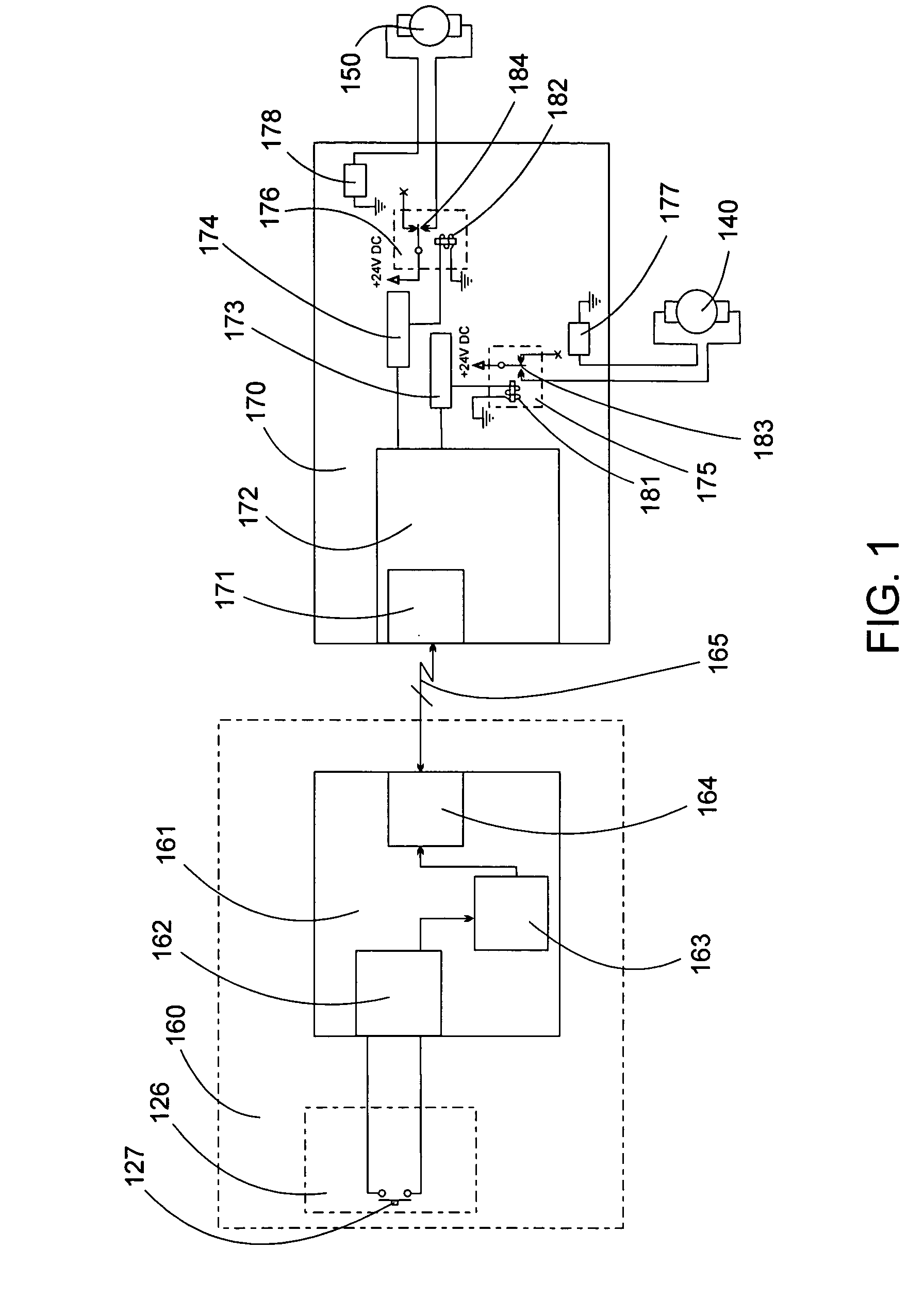
[0039]Referring to FIG. 1, an electrical schematic of an emergency system of the present invention is depicted. A single push-button emergency switch 127 is located on a control panel 126 on a foot board of an electrically operated patient bed. Associated with the control panel 126 is a control panel microcontroller 161, which together form a foot board staff control unit 160. Other control buttons (not shown) are also on the control panel 126 and are associated with the control panel microcontroller 161. The control panel microcontroller 161 comprises, among other elements (not shown), a button decoder 162, a timer 163 and a first UART serial port 164. In an emergency situation, an attendant pushes the emergency switch 127 thereby sending a signal to the button decoder 162 which is programmed to distinguish between the buttons on the control panel. Having determined that the emergency switch 127 was pushed, the button decoder 162 sends a signal to the timer 163 which is programmed ...


PUM


Abstract

An electrically activated emergency system for a patient bed comprises: an electrically powered linear actuator for driving a back rest of the patient bed from a lowered back rest position to a raised back rest position and operable to permit the back rest to lower from the raised back rest position to the lowered back rest position without being driven by the linear actuator; and, an independent emergency back rest lowering feature comprising an electrical activation means for activating the linear actuator to permit the back rest to lower from the raised back rest position to the lowered back rest position without being driven by the linear actuator, the electrical activation means not requiring continued operator attendance for continued lowering of the back rest. The present invention permits an attendant, for example a nurse, to press a single button to bring the back rest to a lowered back rest position without having to keep the button pressed so that the attendant is free to immediately begin administering emergency procedures while the back rest is lowering.

Description

FIELD OF THE INVENTION[0001]The present invention relates to patient beds, particularly to adjustable patient beds for healthcare facilities, such as hospitals and long-term care facilities. In particular, the present invention relates to an emergency system for such beds.BACKGROUND OF THE INVENTION[0002]Patient beds in healthcare facilities are designed so that various parts of the bed can adopt a number of positions to provide for greater patient comfort and / or to facilitate the tasks of an attendant, for example a nurse. For example, beds may be raised or lowered to different heights. Patient support platforms may be tilted to achieve the Trendelenburg and reverse Trendelenburg positions. Patient support platforms may comprise back rests and / or knee rests that can be raised or lowered to support a patient's back and knees in a variety of positions.[0003]Adjusting the position of the bed or parts of the bed may be accomplished by a variety of means, for example, by mechanical, hyd...

Claims


Application Information

Patent Timeline
Patent Type & Authority Patents(United States)
IPC IPC(8): A47B7/02F16H3/06F16H55/02A61G7/012A61G7/015A61G7/018A61G7/05F16H55/00
CPCA61G7/015A61G7/018A61G7/012Y10T74/19735Y10T74/18696
Inventor ROUSSY, RICHARD B.
Owner STRYKER CORP
Why Eureka
Try Eureka