Surveying instrument

a technology of surveying instruments and telescopes, applied in the field of surveying instruments, can solve the problems of a large optical system of telescopes, long time required for collimating operations in conventional surveying instruments, and the view angle of telescopes is generally small, so as to reduce the time necessary for collimating operations.

Inactive Publication Date: 2006-06-06
ASAHI KOGAKU KOGYO KK
View PDF12 Cites 65 Cited by
  • Summary
  • Abstract
  • Description
  • Claims
  • Application Information

AI Technical Summary

Benefits of technology

[0016]According to a surveying instrument to which the present invention is applied, the time necessary for a collimating operation can be reduced with a collimator optical system having a wide viewing angle, together with a telescope optical system; moreover, the time necessary for an auto-collimating operation can be reduced. Furthermore, a survey point can be detected swiftly and collimated precisely by selectively using a telephoto optical system and a wide-angle optical system for detection of the survey point and collimation of the telescope optical system relative to the corner cube.

Problems solved by technology

However, the viewing angle of the telescope optical system is generally small (e.g., approximately one and a half degrees).
Accordingly, a collimating operation takes a long time in conventional surveying instruments.

Method used


Image

  • Surveying instrument
  • Surveying instrument
  • Surveying instrument

Examples


first embodiment

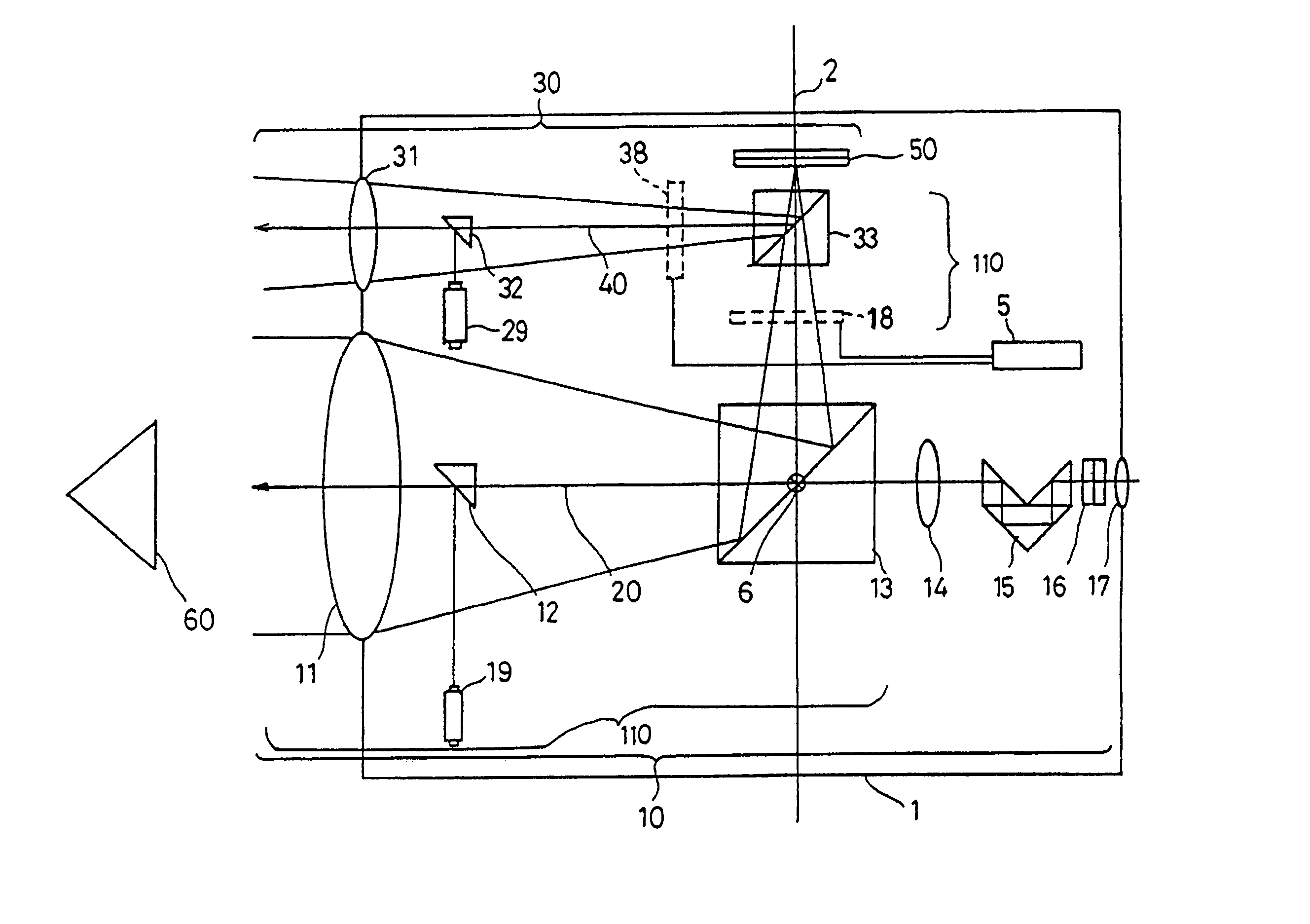
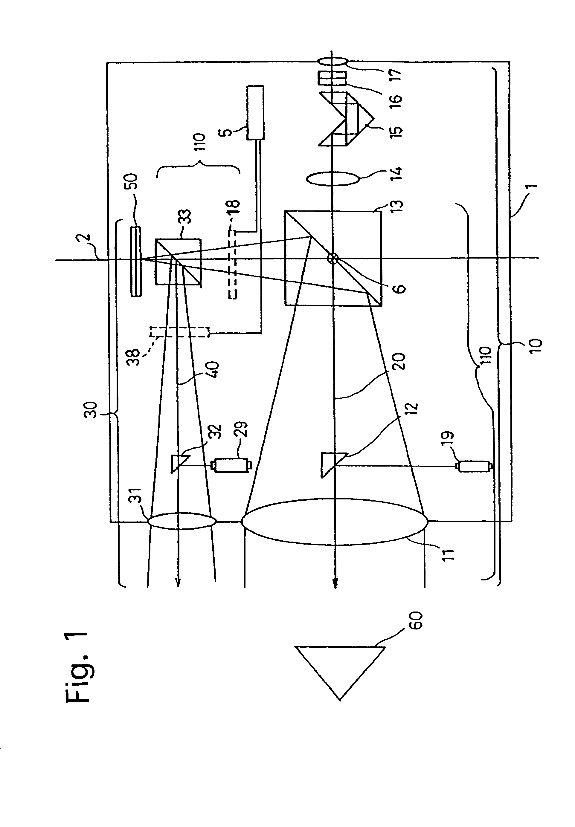
[0027]FIGS. 1 through 4 show a surveying instrument. As shown in FIG. 1, the surveying instrument is provided with a surveying instrument body 1, a telescope optical system 10, a first collimator optical system 30, and a second collimator optical system 110. Light rays which are firstly projected outwards from a light source 29 inside the surveying instrument body 1 to be incident on a corner cube (survey point) 60 and subsequently reflected back toward the surveying instrument body 1 by the corner cube 60 are received by the first collimator optical system 30 so that the coordinates (e.g., the x and y coordinates) of the corner cube 60 on the image sensor 50 are determined. In accordance with this positional information of the corner cube 60, the surveying instrument body 1 is moved so that an image of the corner cube 60 is positioned within a field-of-view 21 of the telescope optical system 10 (the second collimator optical system 110) to thereby collimate the surveying instrument...

second embodiment

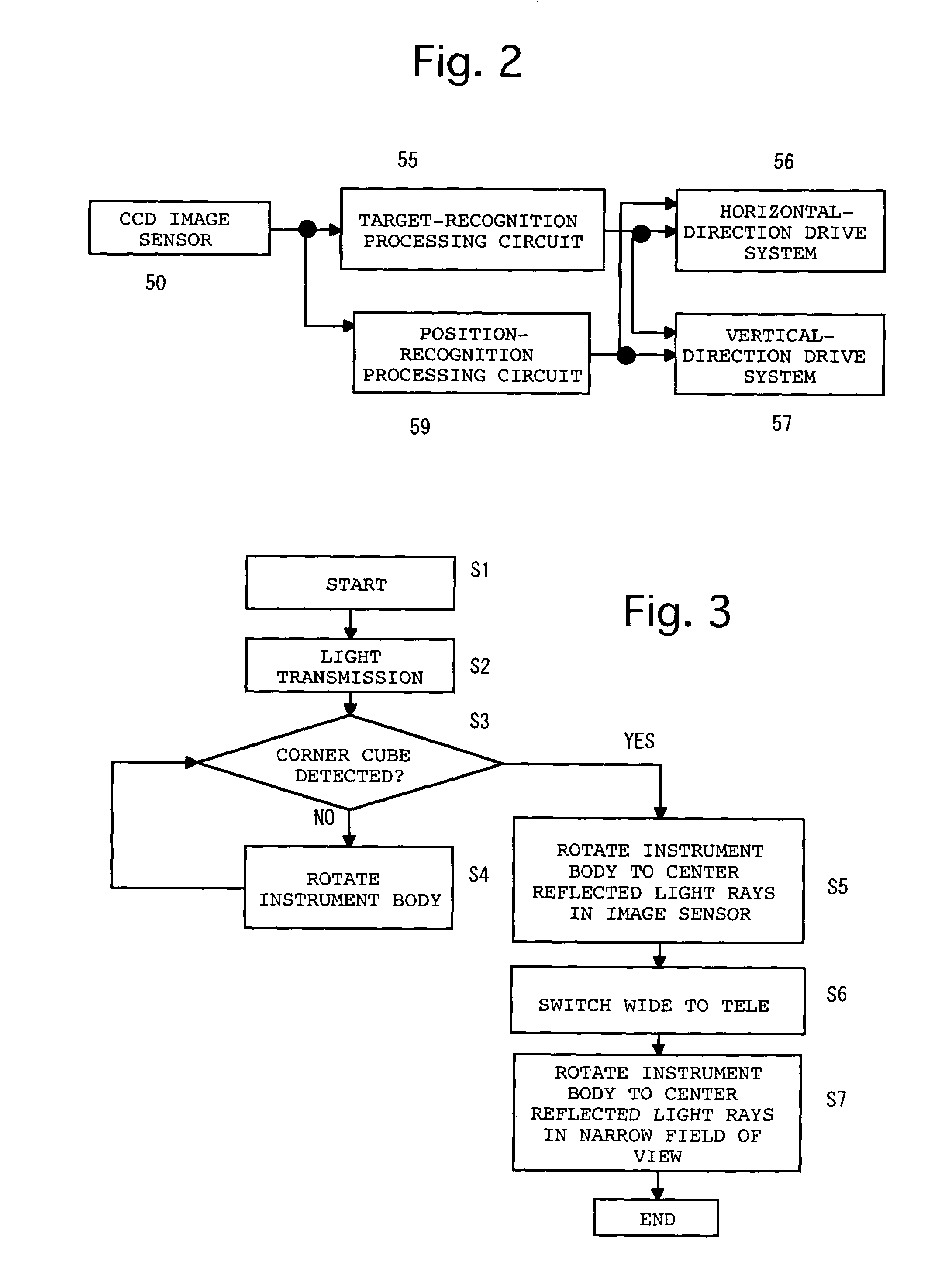
[0047]In the surveying instrument, the target-recognition processing circuit 55 and the position-recognition processing circuit 59 are connected to the image sensor 52.

[0048]A procedure of a collimating operation performed with the second embodiment of the surveying instrument will be hereinafter discussed with reference to FIG. 3. In this procedure, the corner cube 60 is placed at a survey point (step S1). Subsequently, the image sensor 52 is activated, and the light source 79 is turned ON to emit light toward the prism 72 to thereby project light rays toward the corner cube 60 for carrying out a collimating operation (step S2).

[0049]If the image sensor 52 receives light rays reflected by the corner cube 60 (if YES at step S3), it is determined that an image of the corner cube 60 is positioned within the field-of-view 41 of the first collimator optical system 80; based on this determination, the position of an image of the reflected light rays on the image sensor 52 is determined. ...

third embodiment

[0060]A procedure of a collimating operation performed with the surveying instrument will be hereinafter discussed. In this procedure, after the corner cube 60 is placed at a survey point, the image sensor 50 is activated, the zoom mechanism 90 is actuated so that the collimator optical system 130 is set to wide-angle, and the light source 19 is turned ON to emit light toward the right-angle prism 12 to thereby project light rays toward the corner cube 60 for carrying out a collimating operation.

[0061]If the image sensor 50 receives light rays reflected by the corner cube 60, it is determined that an image of the corner cube 60 is positioned within a field-of-view of the collimator optical system 130; based on this determination, the position of an image of the reflected light rays on the image sensor 50 is determined. On the other hand, if the image sensor 50 receives no light rays reflected by the corner cube 60, it is determined that no image of the corner cube 60 is positioned w...


PUM


Abstract

A surveying instrument includes a surveying instrument body rotatable about each of a vertical axis and a horizontal axis; and a first collimator optical system and a second collimator optical system each of which is positioned in the surveying instrument body to collimate the surveying instrument relative to a survey point, a viewing angle of the second collimator optical system being smaller than a viewing angle of the first collimator optical system. A first collimating operation is performed with the first collimator optical system before a second collimating operation is performed with the second collimator optical system.

Description

BACKGROUND OF THE INVENTION[0001]1. Field of the Invention[0002]The present invention relates to a surveying instrument, more specifically to a surveying instrument having a collimator optical system for collimating the surveying instrument through a telescope optical system having a narrow viewing angle.[0003]2. Description of the Related Art[0004]In conventional surveying instruments having a collimator and a telescope optical system for sighting a survey point, a collimator optical system branches from the telescope optical system.[0005]However, the viewing angle of the telescope optical system is generally small (e.g., approximately one and a half degrees). Due to this small viewing angle, with such a collimator optical system, the surveying instrument must be collimated relative to a survey point (e.g., a corner cube) by sequential-scanning of the field-of-view of the collimator optical system while shifting the field-of-view of the collimator optical system due to the field-of...

Claims


Application Information

Patent Timeline
Patent Type & Authority Patents(United States)
IPC IPC(8): G01B11/26G01C1/02G01C15/00
CPCG01C1/02Y10S33/21
Inventor KANEKO, KENJI
Owner ASAHI KOGAKU KOGYO KK
Why Eureka
Try Eureka