Apparatus and method for bending tubing

a technology of bending apparatus and tubing, which is applied in the direction of metal-working apparatus, manufacturing tools, forging/hammering/pressing machines, etc., can solve the problems of less versatile bending apparatus, and achieve the effects of convenient and safe transportation, and convenient and safe transportation

Inactive Publication Date: 2006-06-06
WIDMAYER JOSEPH B
View PDF8 Cites 9 Cited by
  • Summary
  • Abstract
  • Description
  • Claims
  • Application Information

AI Technical Summary

Benefits of technology

[0017]In certain embodiments of this invention, a shaft is rotatably or pivotally mounted with respect to the frame. The bender can have a sleeve or other similar structure for detachably connecting one or more differently sized conventional and / or custom benders, using any suitable mechanical fastener or an adhesive. Using detachable connections for different components of this invention increases the versatility of the bending apparatus, for example by allowing the bending apparatus to accommodate differently sized and / or shaped conduits or tubes. Using fixed or secured connections, such as welded connections, may have a lesser associated cost but may also result in a less versatile bending apparatus.
[0021]When initially loaded into the bending apparatus, the conduit or tube can be supported by a plate or other structural support member. The bending apparatus of this invention can be easily assembled and disassembled into components or pieces that can be conveniently and safely carried to different locations at a construction site, for example to elevated locations accessible by scaffolding, a ladder or steps.
[0023]A method for bending conduit or a tube, according to this invention, can significantly reduce physical stresses to the body of a user, such as an electrician, and can be conveniently and safely transported, assembled, used and disassembled at a job site.

Problems solved by technology

Using fixed or secured connections, such as welded connections, may have a lesser associated cost but may also result in a less versatile bending apparatus.

Method used


Image

  • Apparatus and method for bending tubing
  • Apparatus and method for bending tubing
  • Apparatus and method for bending tubing

Examples


Embodiment Construction

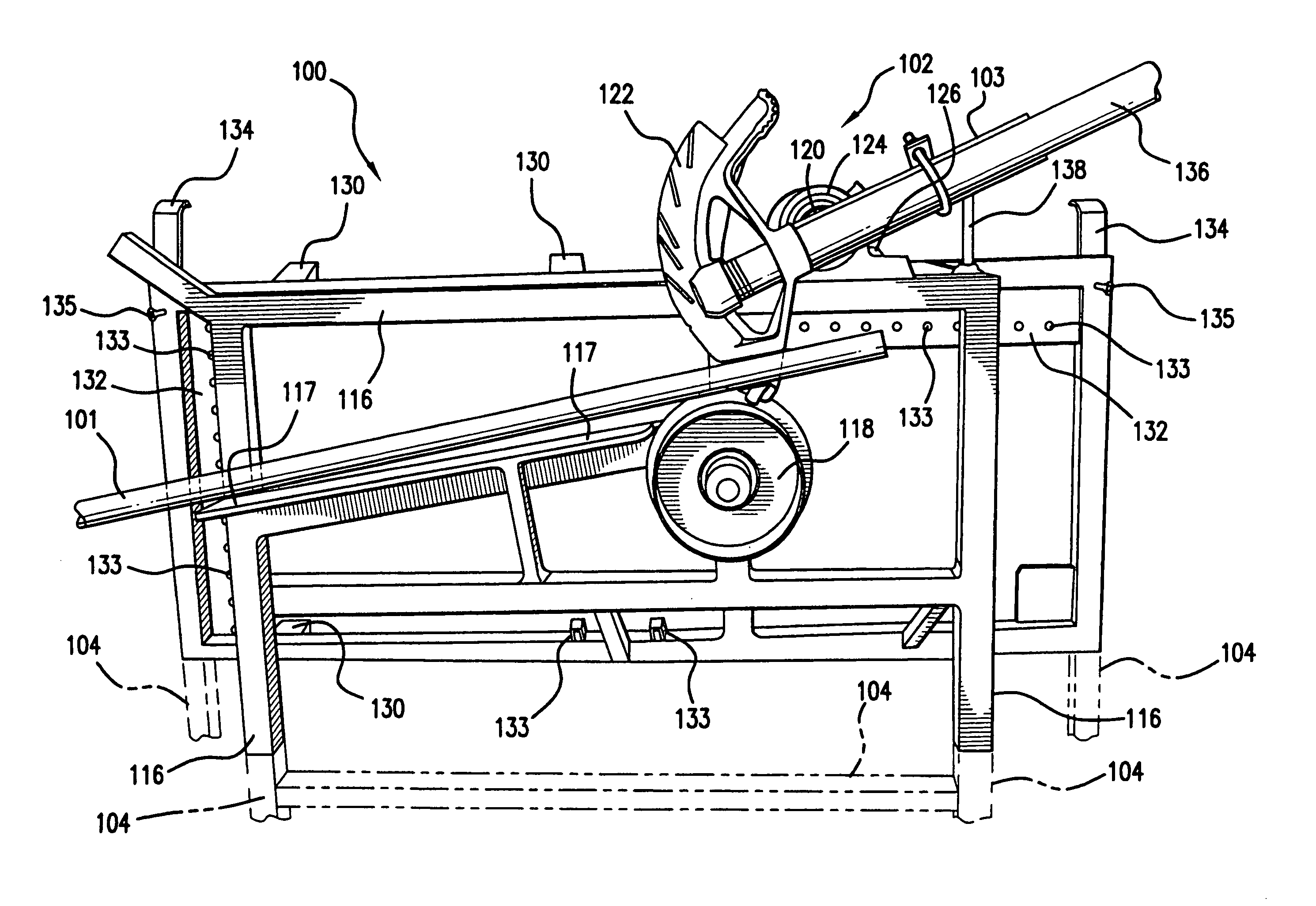
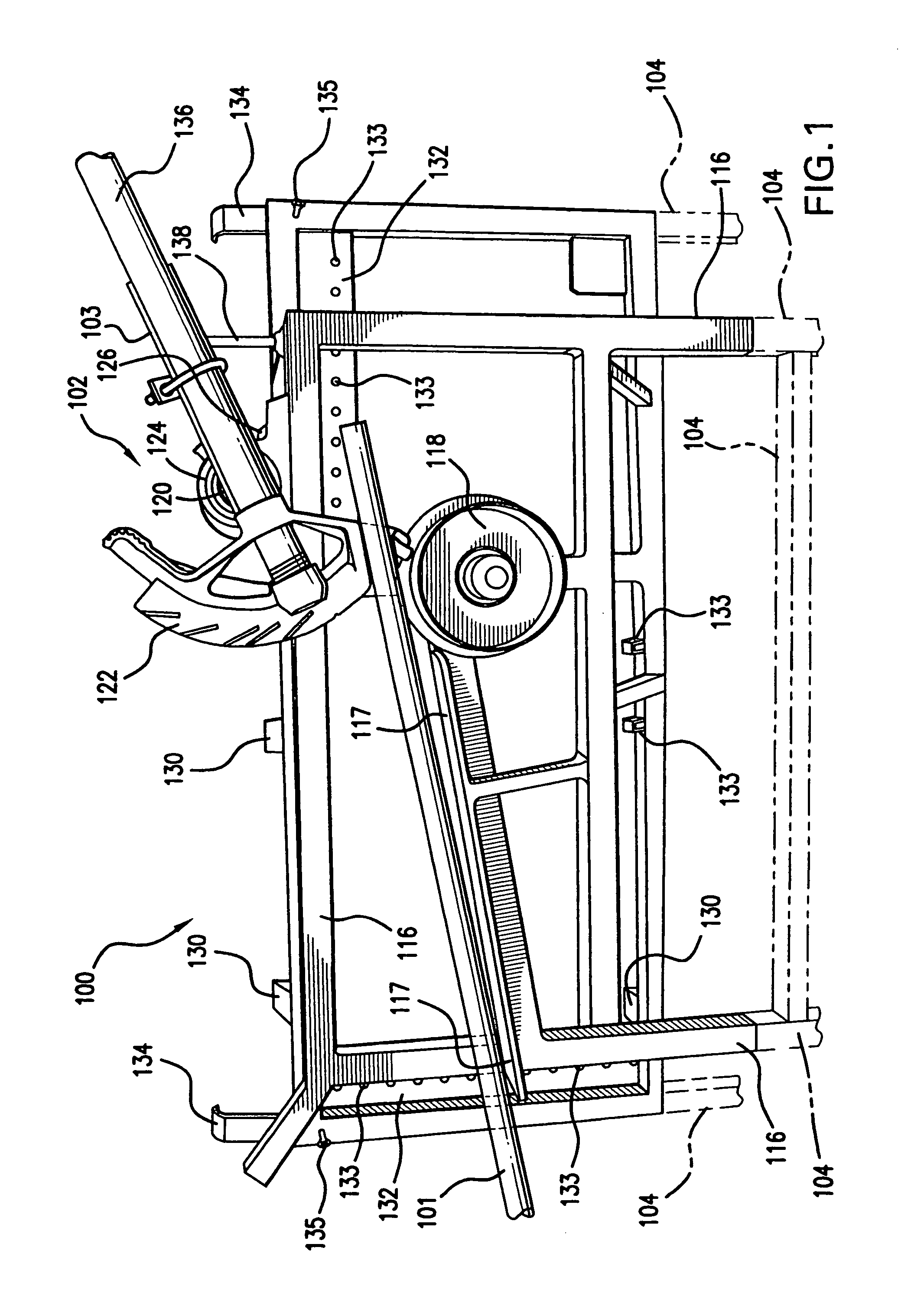
[0027]FIG. 1 shows one embodiment of bending apparatus 100, according to this invention. Bending apparatus 100 can be used to bend a tube, a pipe, a conduit and / or a rod 101. Bending apparatus 100 can be used to bend other elongated members. As used throughout this specification, the term tube is intended to relate to and be interchangeable with any one or more of the terms pipe, conduit, EMT, rod and elongated member. Although bending apparatus 100 is often used for bending conduit such as electrical conduit or EMT, bending apparatus 100 can be used to bend any solid, hollow, tubular or other similar elongated member.

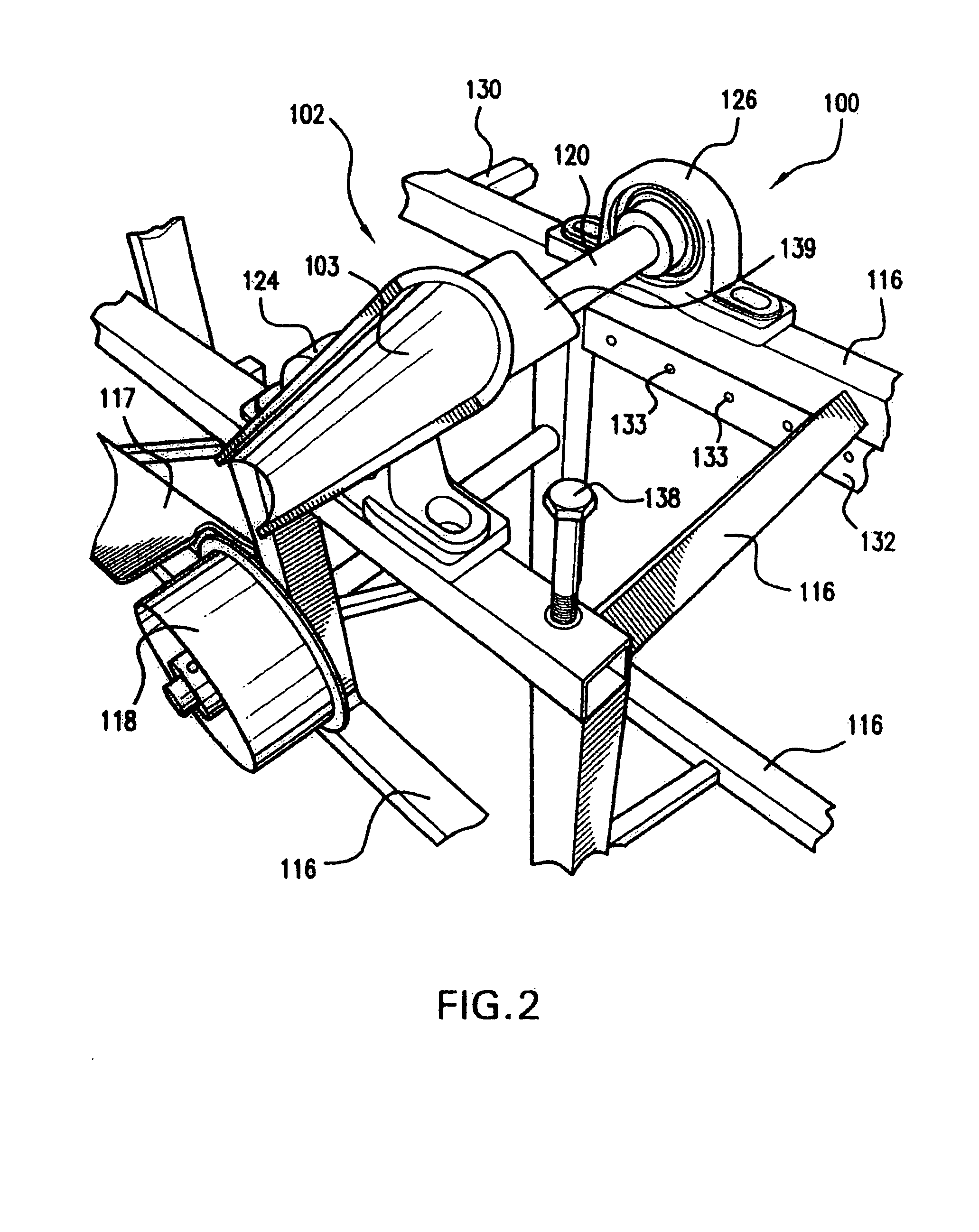
[0028]As shown in FIGS. 1 and 2, bending apparatus 100 comprises frame 116 which enables a user to operate bending apparatus 100 at a convenient height above the ground surface. Stand 104, which is shown in phantom lines in FIG. 1, can be mounted to or positioned under frame 116 for supporting frame 116 at a higher level above a floor or ground surface, for example to ...


PUM

PropertyMeasurementUnit
diameteraaaaaaaaaa
diameteraaaaaaaaaa
distanceaaaaaaaaaa

Abstract

An apparatus and method for bending a tube, a pipe, a conduit and / or a rod. A bender is rotatably mounted with respect to a frame. A guide element, such as a guide roller, is mounted with respect to the frame. The guide element or the guide roller can be fixed or can move with respect to the frame. The combination of the frame, the bender and the guide element can be conveniently transported, assembled, disassembled and used at any job site or construction location.

Description

[0001]This application claims the beneffit of Provisional Application No. 60 / 590,069 filed Jul. 12, 2004.BACKGROUND OF THE INVENTION[0002]1. Field of the Invention[0003]This invention relates to a method and apparatus for bending tubing, such as electrical conduit.[0004]2. Discussion of Related Art[0005]Conventional conduit benders are typically used in the field at a commercial, residential or industrial construction site to bend conduit pipe or electrical metallic tubing (EMT). Power benders are typically used to bend EMT having a diameter greater than about 1 inch. Even though power benders can be used for smaller diameter tubing, hand benders having a shoe and a handle are used to roll the conduit between the hand bender and typically a ground or floor surface. Many commercial, residential and industrial construction sites require hundreds, some even thousands, of custom bent EMT pieces which are typically joined together to form a structured EMT network, sometimes having an ela...

Claims


Application Information

Patent Timeline
Patent Type & Authority Patents(United States)
IPC IPC(8): B21D7/04
CPCB21D7/063
Inventor WIDMAYER, JOSEPH B.
Owner WIDMAYER JOSEPH B
Why Eureka
Try Eureka