Load sensor and seat weight measuring apparatus with a plurality of strain gauges

a technology of strain gauges and sensors, which is applied in the direction of instruments, force/torque/work measurement apparatus, tractors, etc., can solve the problems of not being able to meet at all, sensitivity is unsteady, strain on a portion may exceed the allowable limit, and the portion may be broken

Inactive Publication Date: 2006-06-06
TAKATA CORPORATION
View PDF36 Cites 32 Cited by
  • Summary
  • Abstract
  • Description
  • Claims
  • Application Information

AI Technical Summary

Benefits of technology

The present invention aims to provide a load sensor that can accurately measure weight even when the surrounding temperature changes. This invention is useful for measuring the weight of a seat.

Problems solved by technology

The technical problem addressed in this patent is the need to effectively disperse the deformation stress and unify the distortion on the sensor plate, while also eliminating the influence of temperature on the strain gauges to prevent errors in weight measurement.

Method used


Image

  • Load sensor and seat weight measuring apparatus with a plurality of strain gauges
  • Load sensor and seat weight measuring apparatus with a plurality of strain gauges
  • Load sensor and seat weight measuring apparatus with a plurality of strain gauges

Examples


Embodiment Construction

[0065]Hereinafter, embodiments of the present invention will be described in detail with reference to the drawings. Since the basic structure of the load sensor is identical to that shown in FIGS. 10(A) through 11(C), the detail description of the function will be omitted in the following description of the embodiments. Since the seat load measuring apparatus of the embodiment is identical to that shown in FIG. 9 except the structure of the load sensor, the description of the seat load measuring apparatus will be omitted.

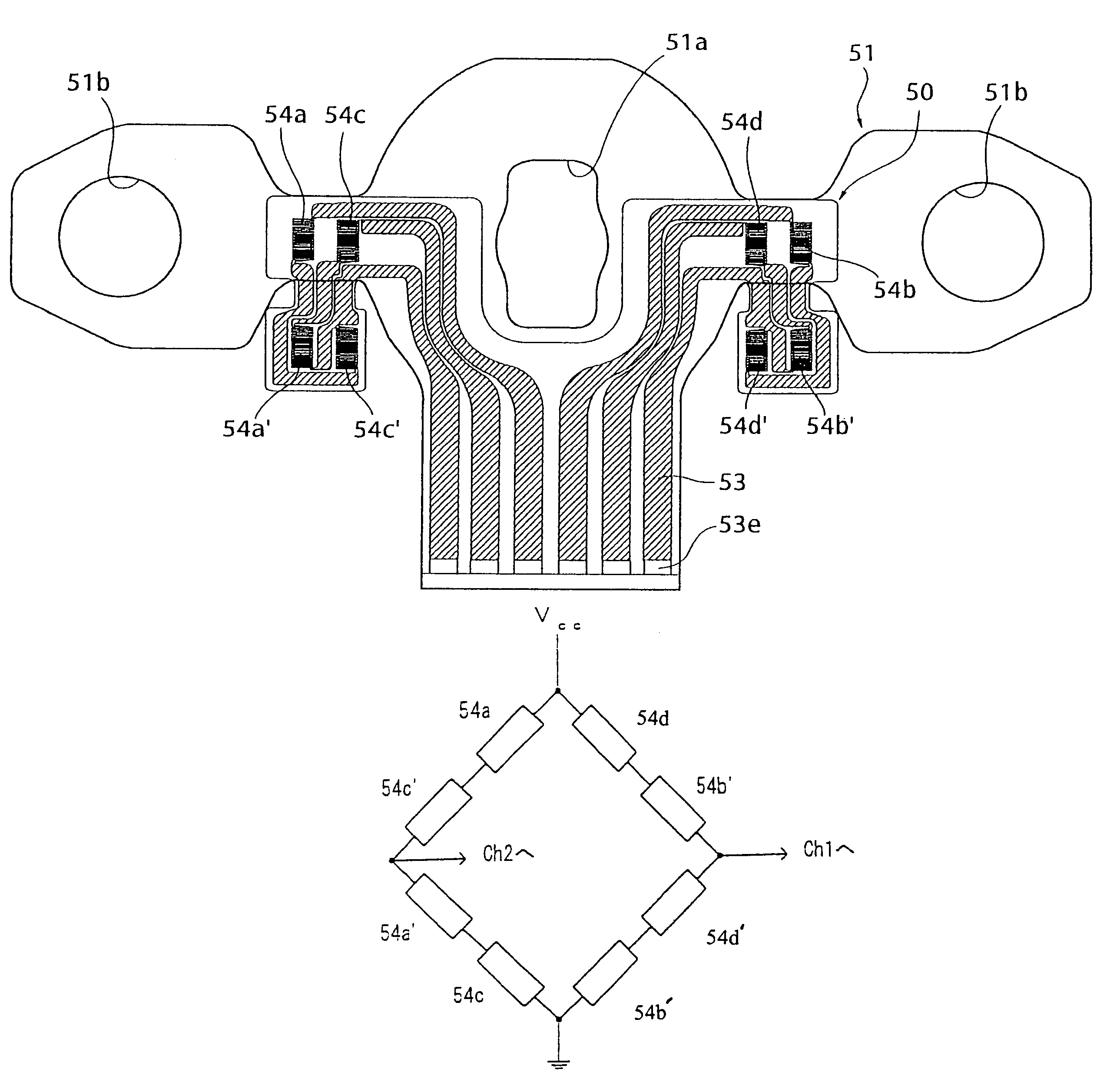
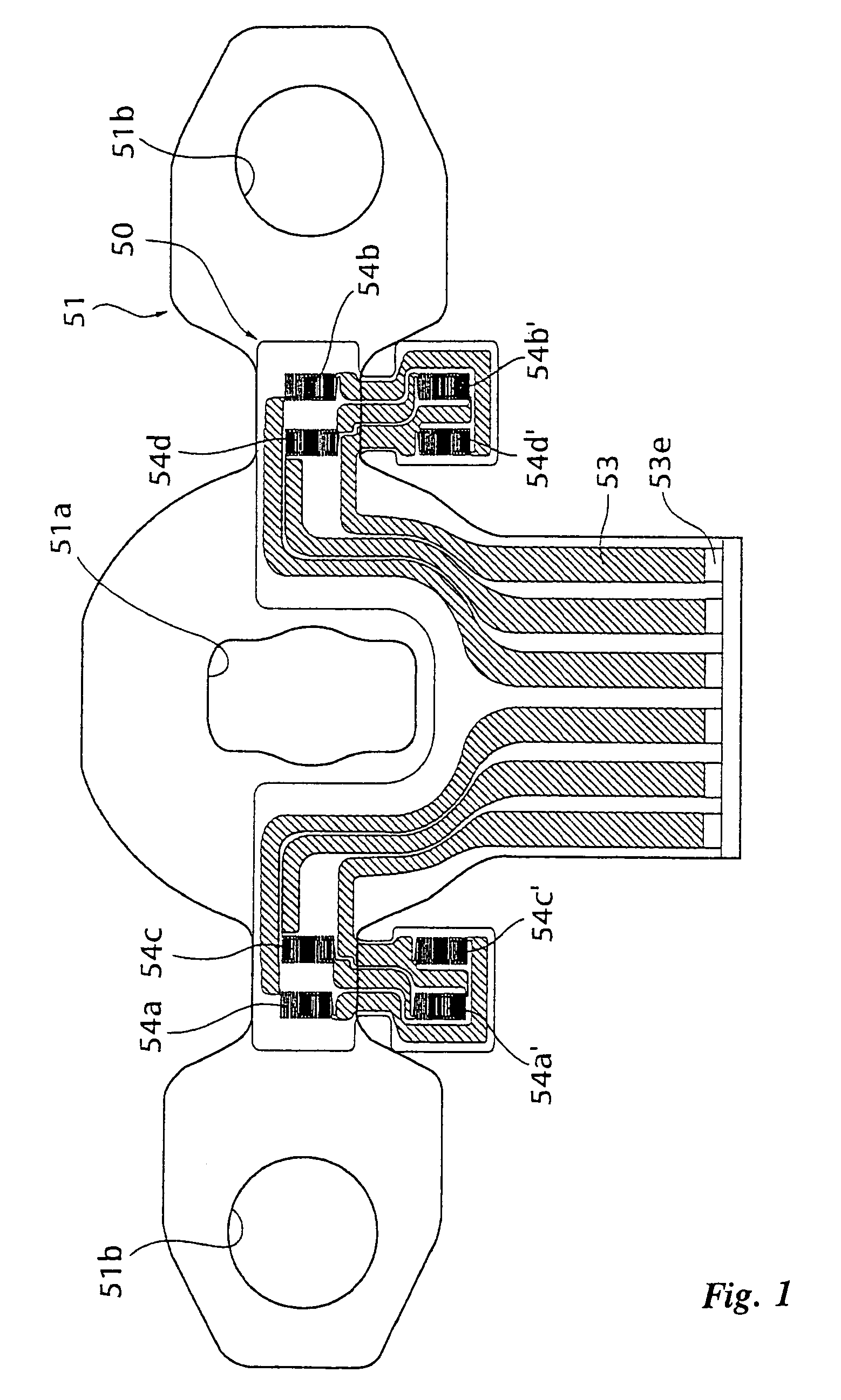
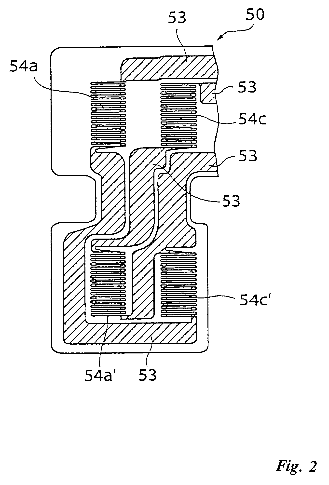
[0066]FIG. 1 is an illustration showing a load sensor of the embodiment of the present invention. In FIG. 1, a numeral 51 designates a sensor plate, which is the same as the sensor plate 37 in FIGS. 10(A), 10(B) and the sensor plate 51 in FIGS. 11(A)–11(C). The holes formed in the sensor plate 51 are marked with the same numerals as used in FIG. 11(A). The description of the holes will be omitted.

[0067]The sensor plate or load sensor 51 includes a sensor 50. The sen...


PUM


Abstract

A load sensor hardly causing error in weight measurement even when the environmental temperature of the load sensor varies, and a seat weight measuring apparatus using the load sensor. The sensor includes a plurality of strain gauges form a bridge circuit. The strain gauges forming the bridge circuit are attached to the front and back surfaces of a base plate at substantially the same location. Portions of a flexible substrate, on which the strain gauges are formed, are folded and adhered to the back of the sensor plate with adhesive. The bridge circuit formed by the strain gauges compensates for the variation in resistance among the strain gauges generated due to the temperature distribution of the base plate, resulting in little or no variation in output.

Description


Claims


Application Information

Patent Timeline
Owner TAKATA CORPORATION
Why Eureka
Try Eureka