Pressure sensor having casing with groove
- Summary
- Abstract
- Description
- Claims
- Application Information
AI Technical Summary
Benefits of technology
Problems solved by technology
Method used
Image
Examples
first embodiment
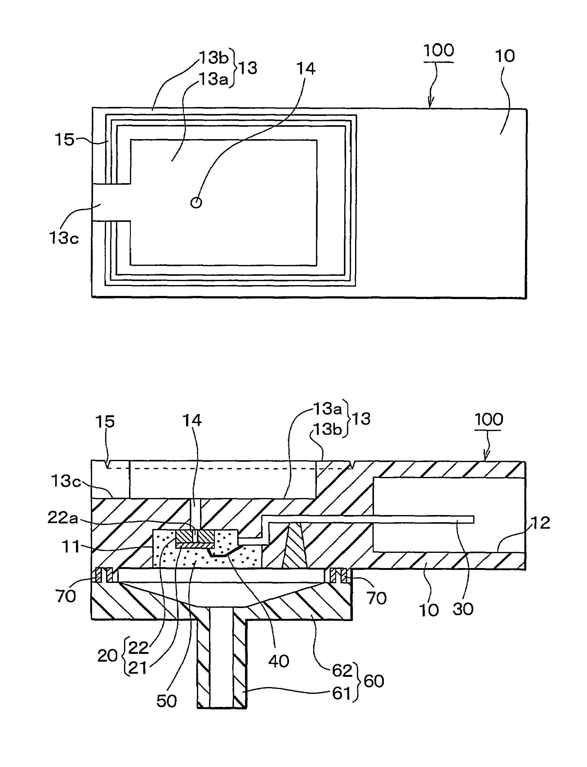
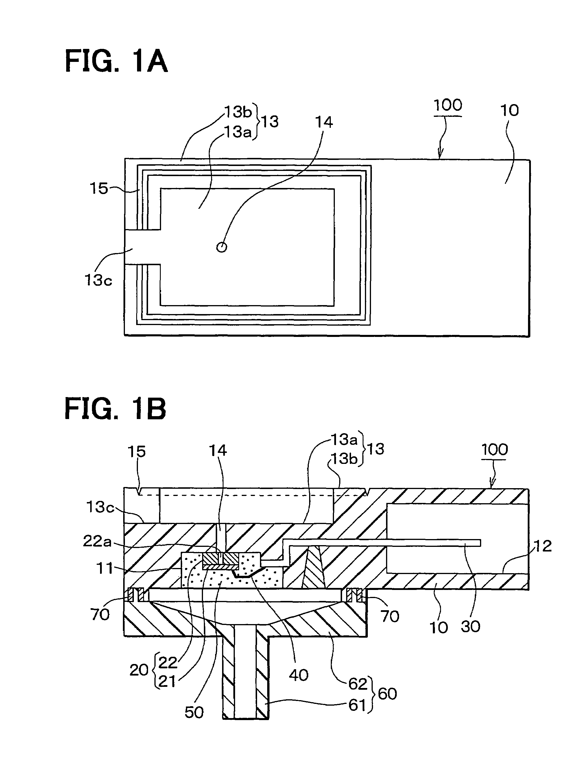
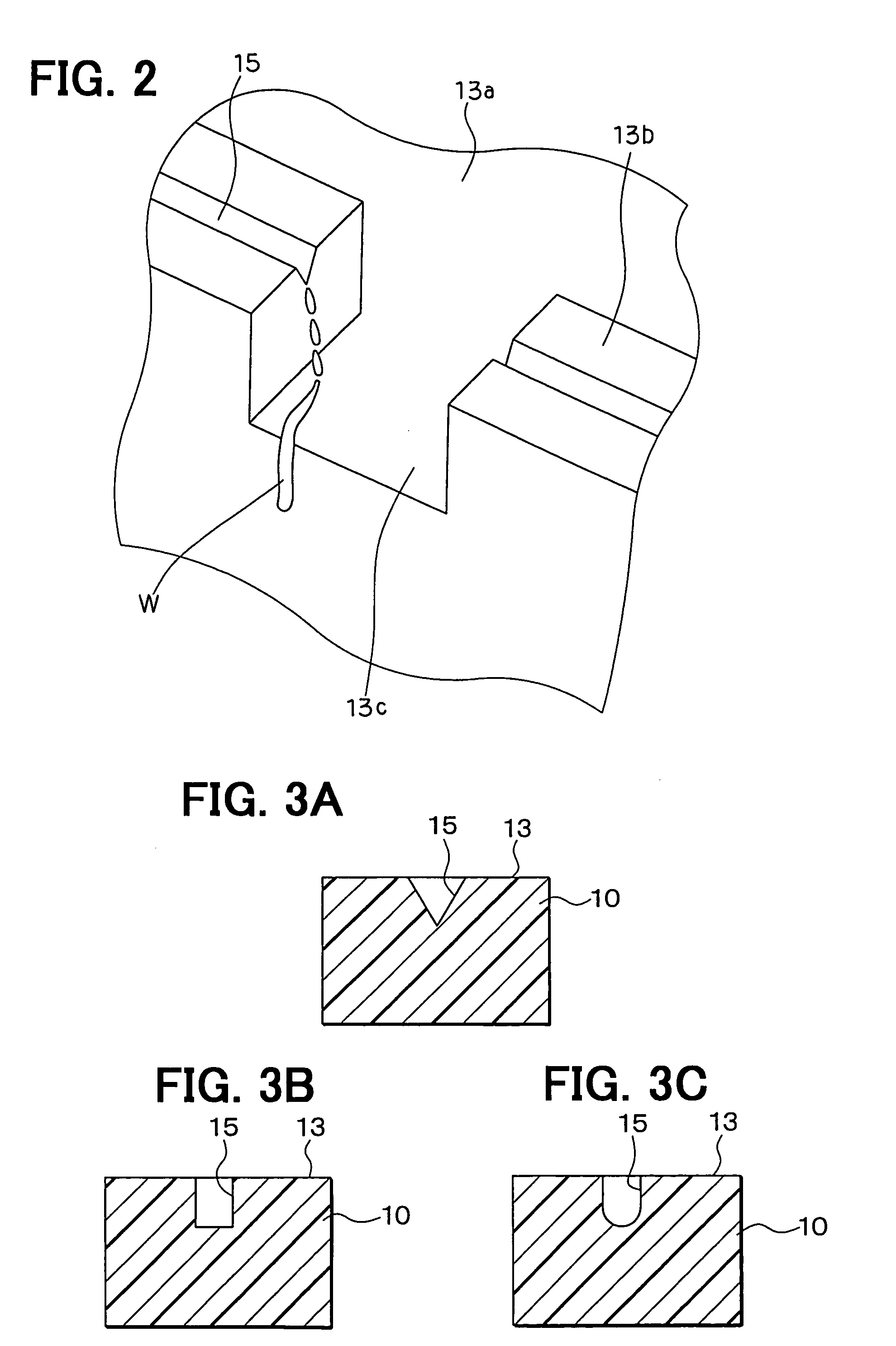
[0022]A pressure sensor 100 according to a first embodiment of the present invention is shown in FIGS. 1A and 1B. The pressure sensor 100, for example, is used for a vehicle. Specifically, the pressure sensor 100 is displaced in an engine compartment of the vehicle so that the pressure sensor 100 works as an intake manifold pressure sensor for detecting intake manifold pressure in an intake manifold of the vehicle.
[0023]The sensor 100 includes a casing 10 made of resin such as PPS (i.e., poly(phenylene sulfide)) or PBT (i.e., poly(butylene terephthalate)). The casing 10 includes a chamber 11 disposed under the casing 10. A sensor chip 20 is disposed in the chamber 11. The sensor chip 20 is provided such that a semiconductor substrate 21 is bonded to a glass base 22 by using an anodic bonding method and the like so as to integrate together. The semiconductor substrate 21 includes a strain gauge (not shown) for detecting pressure applied to the substrate 21. Thus, a pressure signal co...
second embodiment
[0035]A pressure sensor 200 according to a second embodiment of the present invention is shown in FIGS. 4A and 4B. The sensor 200 includes a cover 80 for covering the atmosphere introduction port 14. The cover 80 is made of resin such as PPS or PBT. The cover 80 is attached and fixed to the casing top 13 by press fitting method and the like. Specifically, the cover 80 includes a convexity 81. The convexity 81 of the cover 80 just fits into the concavity 13a of the casing top 13, so that the cover 80 is press-inserted into the casing 10 by using the convexity 81.
[0036]The cover 80 blocks the water drop splashing toward the atmosphere introduction port 14 and jumping over the groove 15. Therefore, the water drop can be surely prevented from penetrating into the atmosphere introduction port 14.
[0037]BY contrary, if the sensor 200 has no cover 80, the water drop may penetrate into the atmosphere introduction port 14 in case of following situation. When the atmosphere temperature around ...
third embodiment
[0039]A pressure sensor 300 according to a third embodiment of the present invention is shown in FIGS. 5A, 5B and 6. The sensor 300 includes multiple grooves 15, which are more than the groove 15 in the sensor 100 shown in FIGS. 1A and 1B. The multiple grooves 15 are formed on the periphery 13b of the casing top 13. Specifically, a part of the grooves 15 extend from a ring-shaped groove 15 surrounding the concavity 13a of the casing top 13 to the sidewall of the casing 10. Further, another part of the grooves 15 are formed on the sidewall of the casing 10, as shown in FIG. 6. Furthermore, further another groove 15 is formed on the notch portion 13c.
[0040]Thus, the sensor 300 with the multiple grooves 15 surely prevents the water drop from penetrating into the atmosphere introduction port 14.
PUM
 Abstract
Description
Claims
Application Information
 - R&D
- Intellectual Property
- Life Sciences
- Materials
- Tech Scout
- Unparalleled Data Quality
- Higher Quality Content
- 60% Fewer Hallucinations
Browse by: Latest US Patents, China's latest patents, Technical Efficacy Thesaurus, Application Domain, Technology Topic, Popular Technical Reports.
© 2025 PatSnap. All rights reserved.Legal|Privacy policy|Modern Slavery Act Transparency Statement|Sitemap|About US| Contact US: help@patsnap.com


