

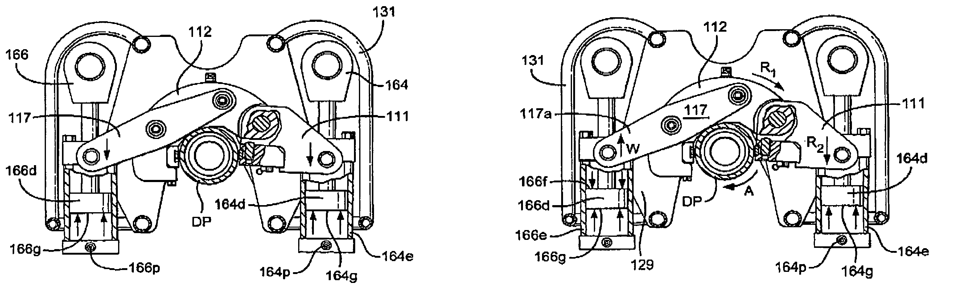
Pipe gripper and top drive systems
a top drive and pipe gripper technology, applied in the direction of drilling pipes, drilling casings, borehole/well accessories, etc., can solve the problems of requiring expensive and time-consuming additional fluid weighting, affecting the drilling process, and affecting the drilling effect of the pipe gripper
- Summary
- Abstract
- Description
- Claims
- Application Information
AI Technical Summary
Benefits of technology
Problems solved by technology
Method used
Image

Examples
Embodiment Construction
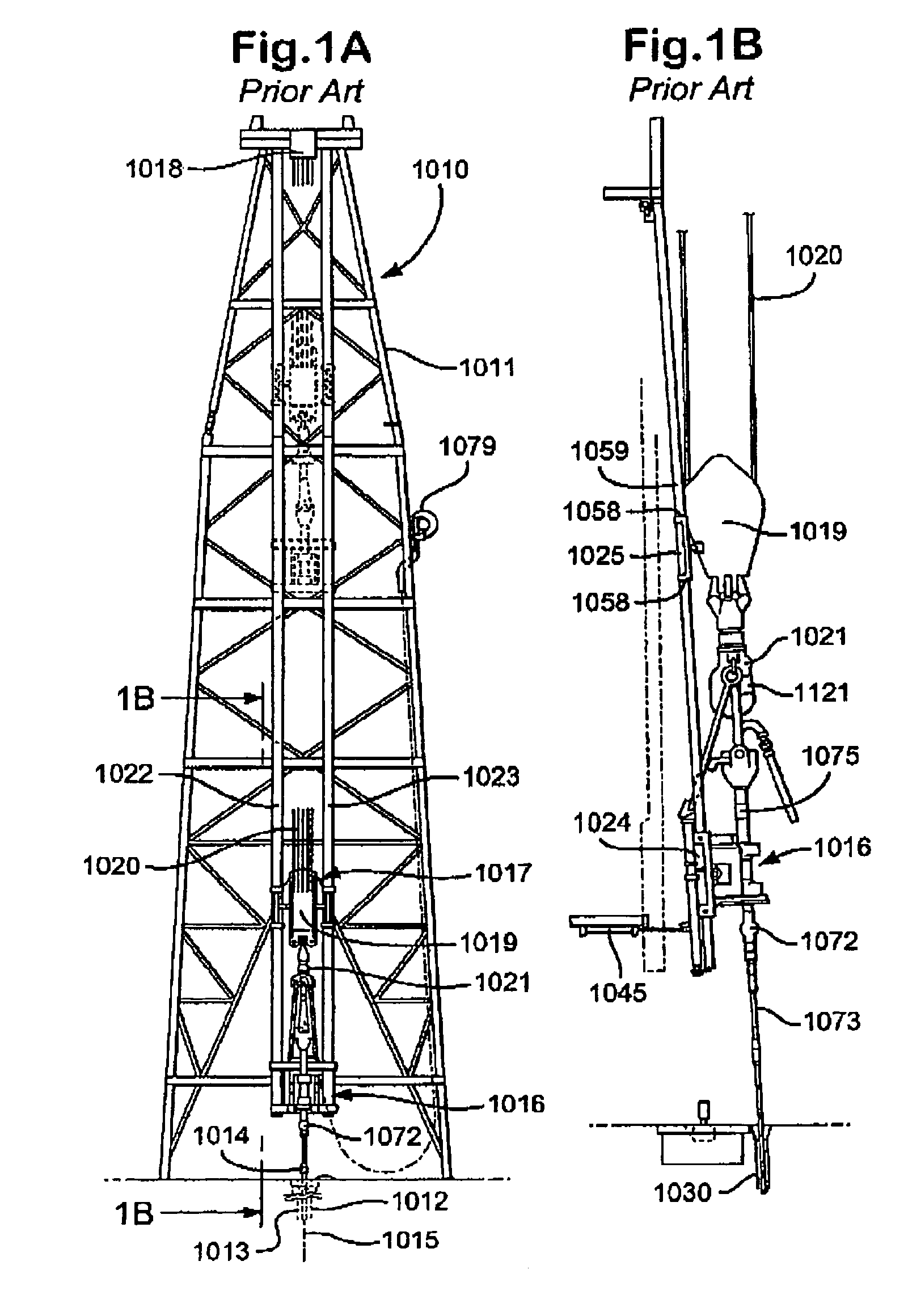
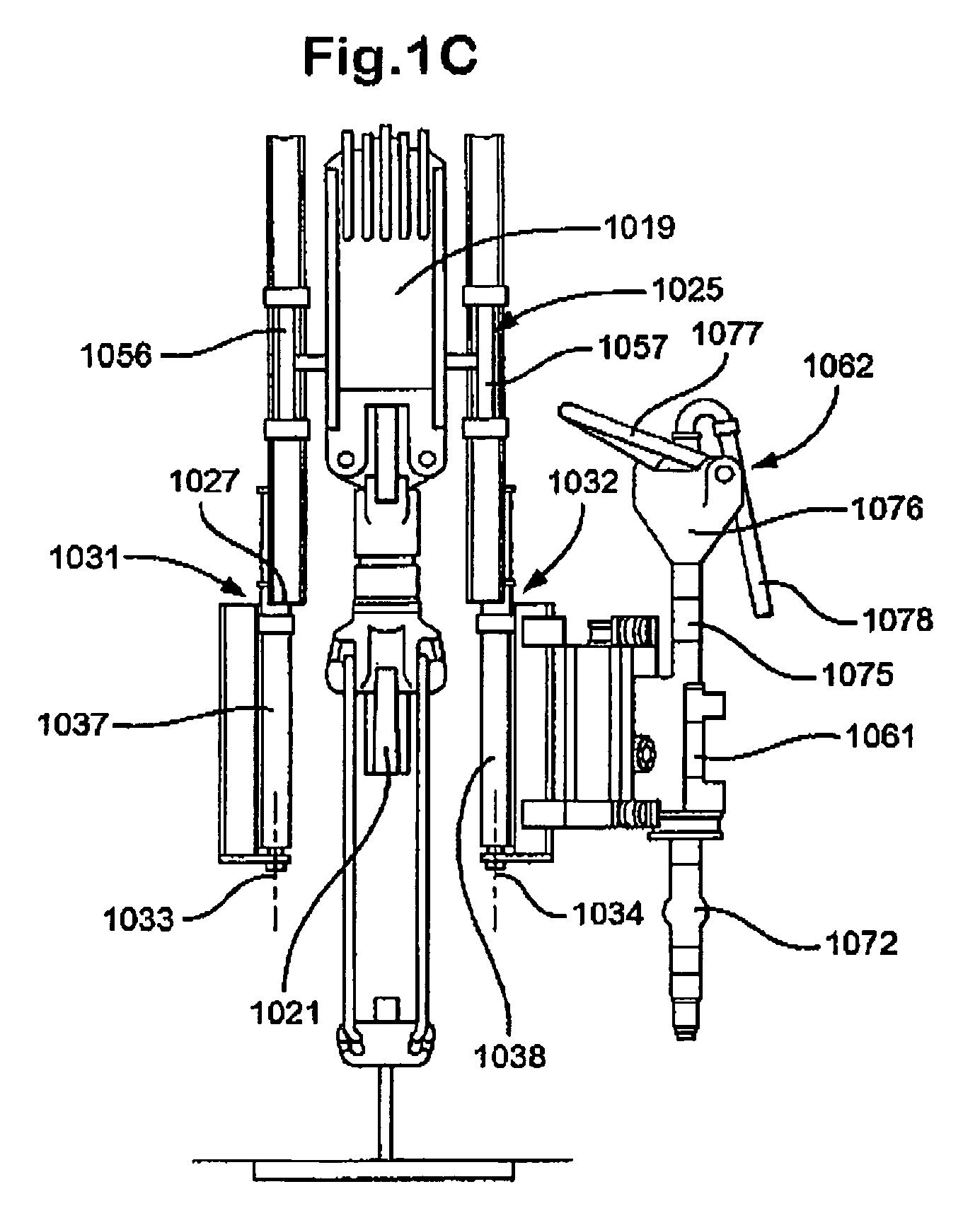
[0033]FIGS. 1A–1C show a prior art rig and top drive system 1010 as disclosed in U.S. Pat. No. 4,458,768 (incorporated fully herein for all purposes).
[0034]The prior art drilling rig 1010 illustrated in FIGS. 1A–1C includes a derrick 1011 projecting upwardly above a location at which a well bore 1012 is being drilled by a rotary drill string 1013 formed in conventional manner in a series of drill pipe stands connected together in end-to-end fashion at threaded connections 1014. The string 1013 is turned about the vertical axis 1015 of the well by a drilling unit 1016 connected to the upper end of the string. The drill string and unit 1016 are supported and adapted to be moved upwardly and downwardly by a hoisting mechanism 1017 including a crown block 1018, traveling block 1019, tackle 1020, supporting block 1019 from block 1018, and power driven draw works for reeling the line 1020 in or out to raise or lower the traveling block. The traveling block supports a hook 1021 from which ...
PUM
 Abstract
Description
Claims
Application Information