Landing gear and method of assembly

Active Publication Date: 2006-06-06
THE HOLLAND GROUP
View PDF20 Cites 22 Cited by
  • Summary
  • Abstract
  • Description
  • Claims
  • Application Information

AI Technical Summary

Benefits of technology

[0007]Among the several objects and features of the present invention may be noted the provision of landing gear which is of simplified construction; the provision of such landing gear having a compact gear arrangement; the provision of such landing gear which provides additional torque in low gear and augmentation of crank rotation in high gear to increase speed; the provision of such a landing gear which inhibits leakage of lubricant; the provision of such landing gear which has fewer external bearings receiving shafts; the provision of such landing gear which has fewer parts; the provision of such landing gear which is lighter in weight; and the provision of such landing gear which can be efficiently assembled.
[0008]Further among the several objects and features of the present invention may be noted the provision of a method of assembling landing gear which can be carried out rapidly and with precision; the provision of such a method which reduces the number of externally exposed shaft bearings to minimize leakage; and the provision of such a method which reduces the number of steps to complete manufacture of the landing gear.
[0009]In general, one embodiment of the invention is directed to landing gear for selectively supporting a semitrailer. The landing gear includes a leg having an upper section and a lower section in telescoping arrangement with each other and a lead screw mounted for extending and retracting the upper and lower sections relative to each other upon rotation of the lead screw. The landing gear also includes an input shaft for applying a torque to the lead screw to drive rotation thereof, the input shaft being rotatable about a first rotation axis and movable in translation along the first rotation axis for shifting between a first position for low gear operation and a second position for high gear operation. The landing gear also includes an output shaft including an output gear for transmitting torque to the lead screw, the output shaft being mounted for rotation about a second rotation axis and being generally axially aligned with the input shaft. The landing gear also includes a gearing subassembly configured so that for each rotation of the input shaft, the output shaft rotates less than one rotation for low gear operation and interconnecting the generally axially aligned input and output shafts in the second position so that for each rotation of the input shaft, the output shaft rotates more than one rotation, whereby the gearing subassembly augments lift when the input shaft is in the first position and augments speed in the second position.

Problems solved by technology

The semitrailers are very large and heavy by themselves, and further carry large loads.
Once the load is relieved from the leg, such as when the semitrailer is supported by the tractor, the slow linear movement of the lower leg section becomes an issue because of the long time it takes to get the lower leg section retracted far enough above the ground for safe travel over the road.
Likewise, slow extension of the lower leg section into engagement with the pavement is also highly undesirable.

Method used


Image

  • Landing gear and method of assembly
  • Landing gear and method of assembly
  • Landing gear and method of assembly

Examples


Embodiment Construction

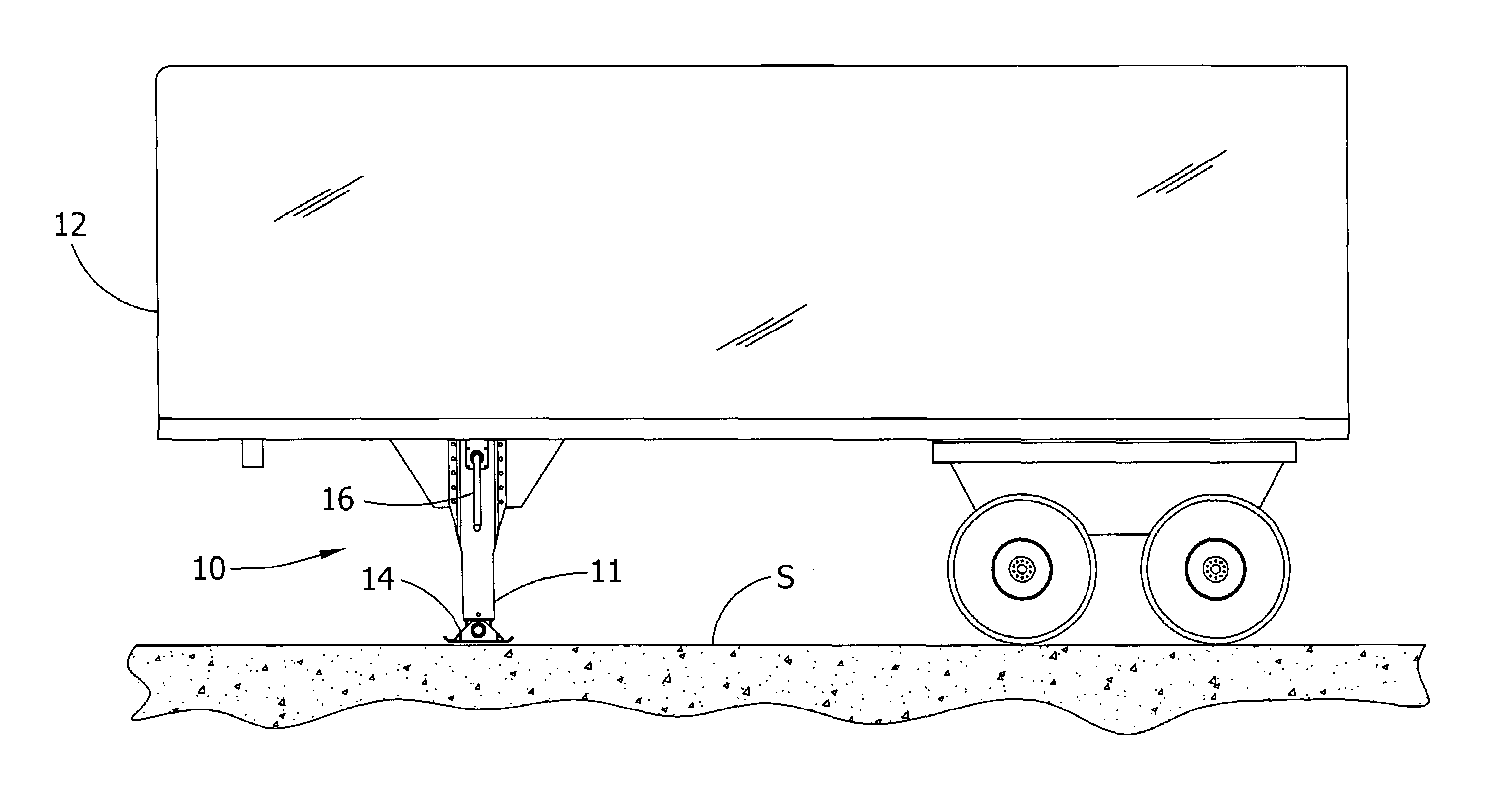
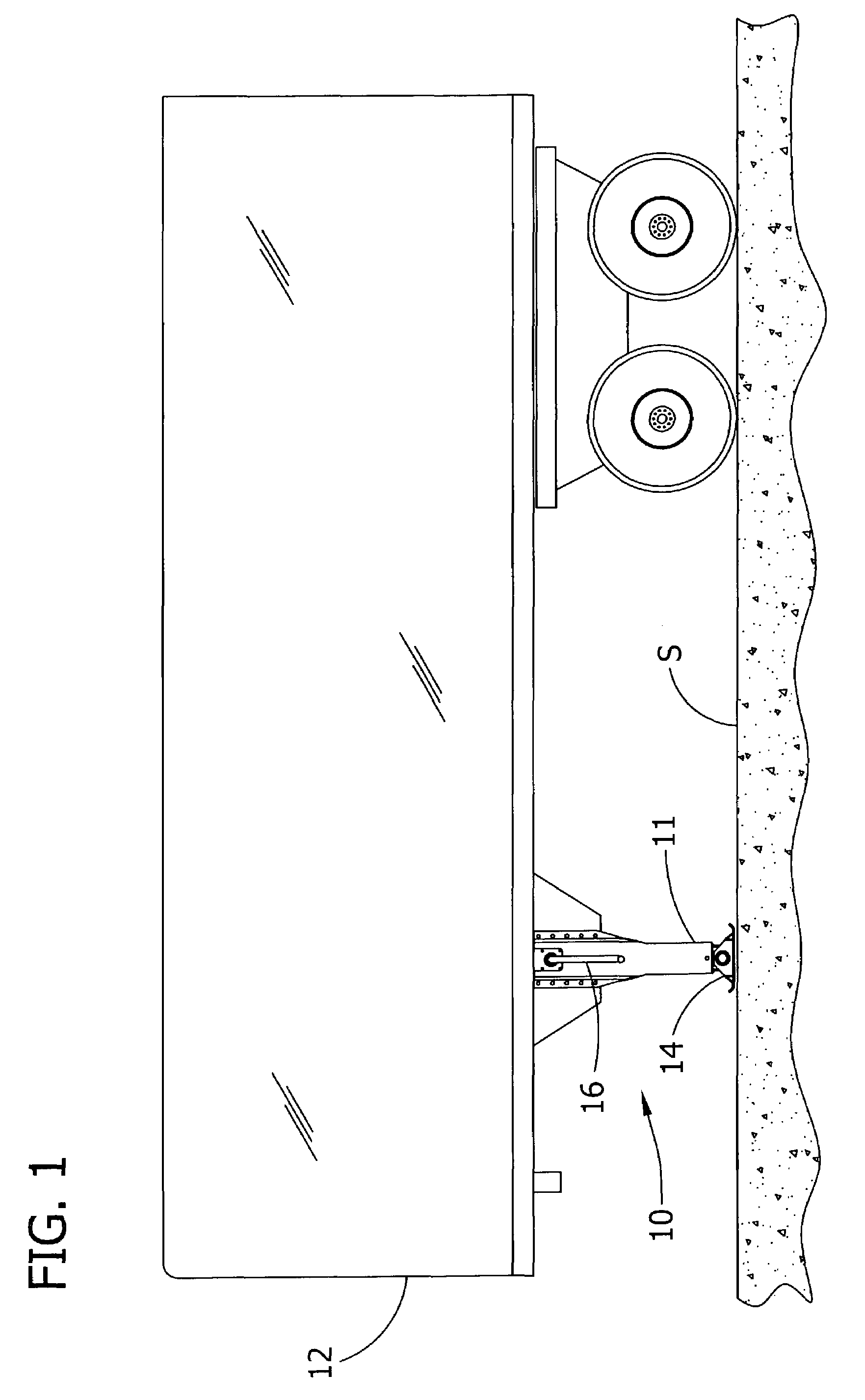
[0046]FIG. 1 illustrates landing gear, indicated generally at 10, for the support of semitrailers when not attached to a tractor. The landing gear 10 typically includes a pair of legs 11 (only one leg is shown) located near respective front corners of a semitrailer 12. Each leg 11 is capable of extending to engage the pavement S or other supporting surface to hold up the front end of the semitrailer as is well understood in the art. A shoe 14 of the landing gear 10 is pivotally mounted on the leg 11 for engaging the pavement S. The legs 11 are also capable of retracting to move up out of the way when the semitrailer 12 is being pulled over the road by a tractor (not shown). A crank handle 16 is used to extend and contract the length of the leg 1, as will be described below. The following description is confined to one of the legs 11. The other leg (not shown) has a similar construction, but if it is connected to gearing of the illustrated leg such as by an output shaft extending und...


PUM


Abstract

Landing gear for selectively supporting a semitrailer and a method of assembly of the landing gear is provided. The landing gear includes a leg having an upper section and a lower section telescopingly received in the upper section. A lead screw extends and retracts the upper and lower sections relative to each other upon rotation thereof. An input shaft applies a torque to the lead screw to drive rotation thereof, the input shaft being rotatable about a rotation axis and movable in translation along the rotation axis for shifting between a first position for low gear operation and a second position for high gear operation. An output shaft, axially aligned with the input shaft, has an output gear for transmitting torque to the lead screw. A gearing subassembly is received in the upper leg section and is configured to augment lift when the input shaft is in the first position and augment speed in the second position.

Description

CROSS REFERENCE TO RELATED APPLICATION[0001]This application claims the benefit of U.S. Provisional Application No. 60 / 369,502, filed Apr. 2, 2002, titled LANDING GEAR AND METHOD OF ASSEMBLY.BACKGROUND OF THE INVENTION[0002]This invention relates generally to landing gear used in the support of semitrailers and more particularly to gearing configurations of a landing gear.[0003]Landing gear of the present invention has particular application in the support of semitrailers when they are not attached to a tractor. The landing gear conventionally includes a pair of telescoping legs capable of extending to engage the pavement or other supporting surface to hold up the front end of the semitrailer, and of retracting to move up out of the way when the semitrailer is being pulled over the road by a tractor. The extension and retraction is most often carried out by the driver manually turning a crank connected by gearing to a lead screw in the leg. The lead screw interconnects telescoping l...

Claims


Application Information

Patent Timeline
IPC IPC(8): B60S9/04B60S9/08
CPCB60S9/08Y10T74/19307
Inventor PEVELER, MICHAEL W.
Owner THE HOLLAND GROUP
Why Eureka
Try Eureka