
Molded flare assembly

a technology of molded flares and assembly parts, which is applied in the direction of bends, pipe joints, pipe elements, etc., can solve the problems of lack of precision in the finished part, time-consuming and inefficient process of hot flaring molded fittings, and skilled technicians with special tools and equipment, etc., to achieve accurate and repeatable results and simple assembly

Inactive Publication Date: 2006-06-06
HAYES JR FR F
View PDF33 Cites 0 Cited by
  • Summary
  • Abstract
  • Description
  • Claims
  • Application Information

AI Technical Summary

Benefits of technology

"This patent describes a technique for making a flare fitting for tubes. The flare is fully formed and inserted into the fitting, and a collet assembly is assembled around the tube. This collet assembly is then snapped into a mating nut, and a retaining cap is snapped onto the nut to complete the assembly. The fully molded flared fitting bodies are accurate and repeatable, and the assembly process is simple. The technical effect of this patent is to provide a reliable and easy-to-assemble flare fitting for tubes."

Problems solved by technology

Hot flaring molded fittings is a time consuming and inefficient process, requiring skilled technicians with special tools and equipment.
Another disadvantage is that hand forming the flare results in lack of precision in the finished part.
The trueness of the flared end with respect to the nominal tube fitting axis suffers due to the hand forming.
The resulting parts are low tolerance, and this can result in a buildup of tolerances when many fittings are employed in an installation.
The hot flaring technique has also been implemented in semi-automated and automated systems, yet parts fabricated using semi-automated or fully automated systems have been found to have problems of lack of trueness and low tolerances.

Method used


Image

  • Molded flare assembly
  • Molded flare assembly
  • Molded flare assembly

Examples


Embodiment Construction

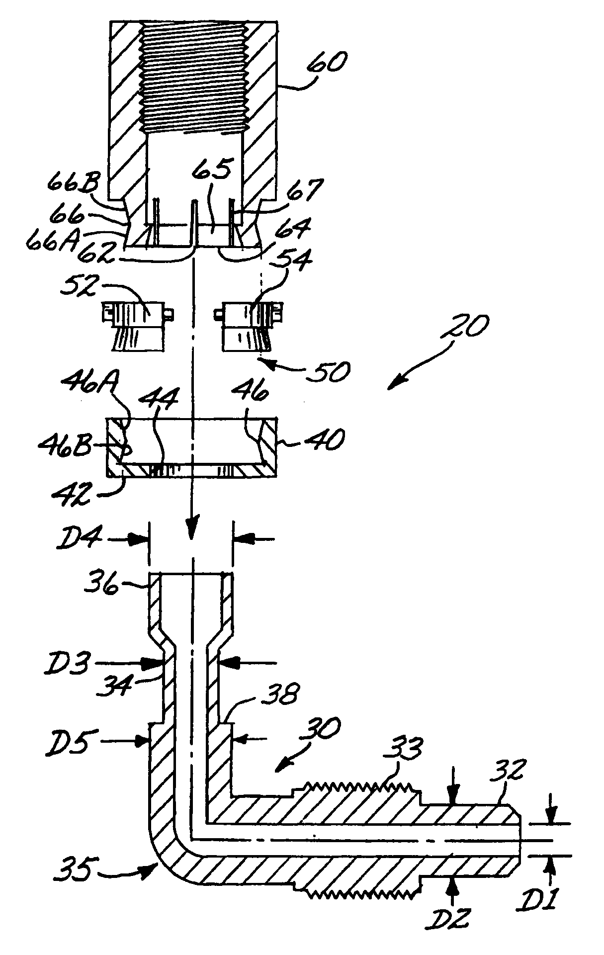
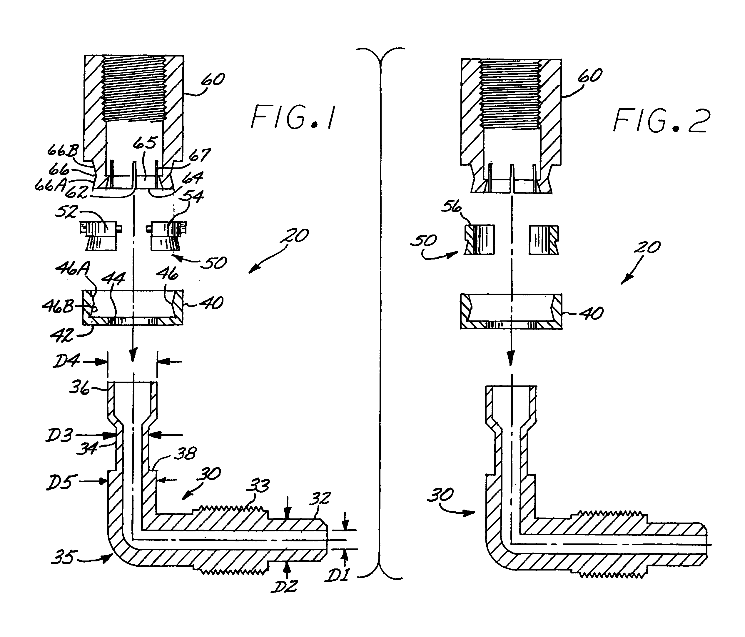
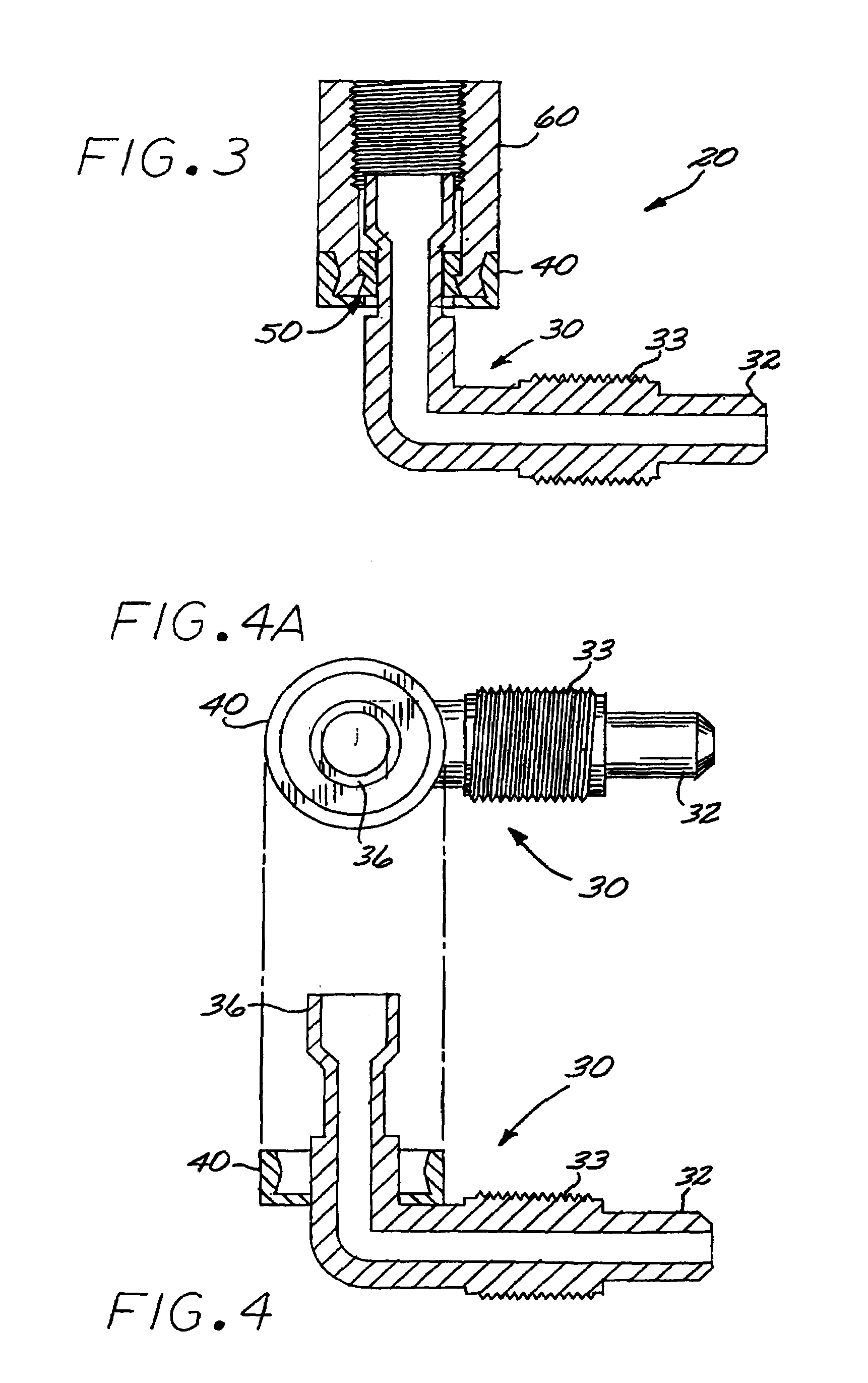
[0021]FIGS. 1–6 illustrate an exemplary embodiment of a right angle flared fitting 20 in accordance with aspects of the invention. The fitting 20 is a right angle fitting comprising a fully molded flare body 20, injection molded from a material such as perfluoroalkoxy (PFA), or other melt-processable fluoropolymers or melt-processable polymers such as polypropylene. The body part 30 is fully formed in the molding process, wherein a male end 32 is formed having an inner diameter D1 and an outer diameter D2, and a threaded outer peripheral portion 33. A right angle is defined between the male end and the flared female end 36. End 36 has an outer diameter D3 at portion 34, and is flared to form female flared end 36 having a maximum outer diameter D4. Portion 34 has a smaller outer diameter D3 than dimension D4 or dimension D5 at the right angle portion 35, thus defining a shoulder 38 on the molded body part 30.

[0022]The fitting 20 further includes a retaining cap 40, a collet assembly ...


PUM

PropertyMeasurementUnit
widthaaaaaaaaaa
widthaaaaaaaaaa
widthaaaaaaaaaa

Abstract

A fully formed flared portion is molded as part of the main body of the one embodiment of the fitting. The flared portion is inserted through the back side of a retaining cap. A collet assembly is assembled together around the smallest diameter of the tube fitting below the flare. The collet assembly is fitted into the top of a mating nut. The retaining cap is then snapped onto the top of the nut, completing the assembly.

Description

CROSS-REFERENCE TO RELATED APPLICATION[0001]This application claims priority from provisional application No. 60 / 305,002, filed Jul. 12, 2001, the entire disclosure of which is incorporated herein by this reference.BACKGROUND OF THE DISCLOSURE[0002]A typical type of flared plastic fitting used for fluid flow applications has a flared tube end with a mating nut positioned inboard of the flared end to couple to a corresponding flared fitting. Conventional plastic flared fittings, such as a right angle fitting, are fabricated by molding a straight tube extension as part of the main body of the fitting. The tube extension is heated to a softened state, which can typically take two to three minutes. The tube extension is then inserted through the back side of the mating nut, pushed onto a forming mandrel and allowed to cool. After cooling, which may take on the order of five minutes to as much as ten to twelve minutes for some processes, the mandrel is removed from the now formed flared ...

Claims


Application Information

Patent Timeline
Patent Type & Authority Patents(United States)
IPC IPC(8): F16L25/00F16L19/02
CPCF16L19/0231Y10T29/49428Y10T29/49945Y10T29/5367
Inventor HAYES, JR., FRANK F.
Owner HAYES JR FR F
Learn More