
Apparatus and Method for Magnetically Unloading a Rotor Bearing

a technology of rotor bearing and magnetic unloading, which is applied in the field of rotors, can solve the problems of large bearings, limited ball bearing lifetime, and roller bearings capable of supporting large weights are necessarily large and expensive, and achieve the effect of accurately prescribing the residual axial preload

Active Publication Date: 2018-03-22
AMBER KINETICS
View PDF7 Cites 3 Cited by
  • Summary
  • Abstract
  • Description
  • Claims
  • Application Information

AI Technical Summary

Benefits of technology

The present invention provides a rotor support system that unloads most of the weight from the bearings of a vertical rotor. This is achieved by using a magnetic lifting force to counteract the force of gravity on the rotor. The system includes a flywheel housing, a rotor with a magnetic material, a magnet, an upper bearing, and a bearing housing. The invention has technical benefits over previous methods, including precise and repeatable magnetic actuation, minimal power requirements, and a maintained axial preload force on the upper bearing.

Problems solved by technology

While the use of rolling bearings to support rotors is effective, the typical use of such bearings requires large bearings.
Roller bearings capable of supporting large weights are necessarily large and expensive.
In addition, as is known in the field, ball bearing lifetime is limited by raceway fatigue, and scales inversely with the cubic power of the bearing load.

Method used


Image

  • Apparatus and Method for Magnetically Unloading a Rotor Bearing
  • Apparatus and Method for Magnetically Unloading a Rotor Bearing
  • Apparatus and Method for Magnetically Unloading a Rotor Bearing

Examples


first embodiment

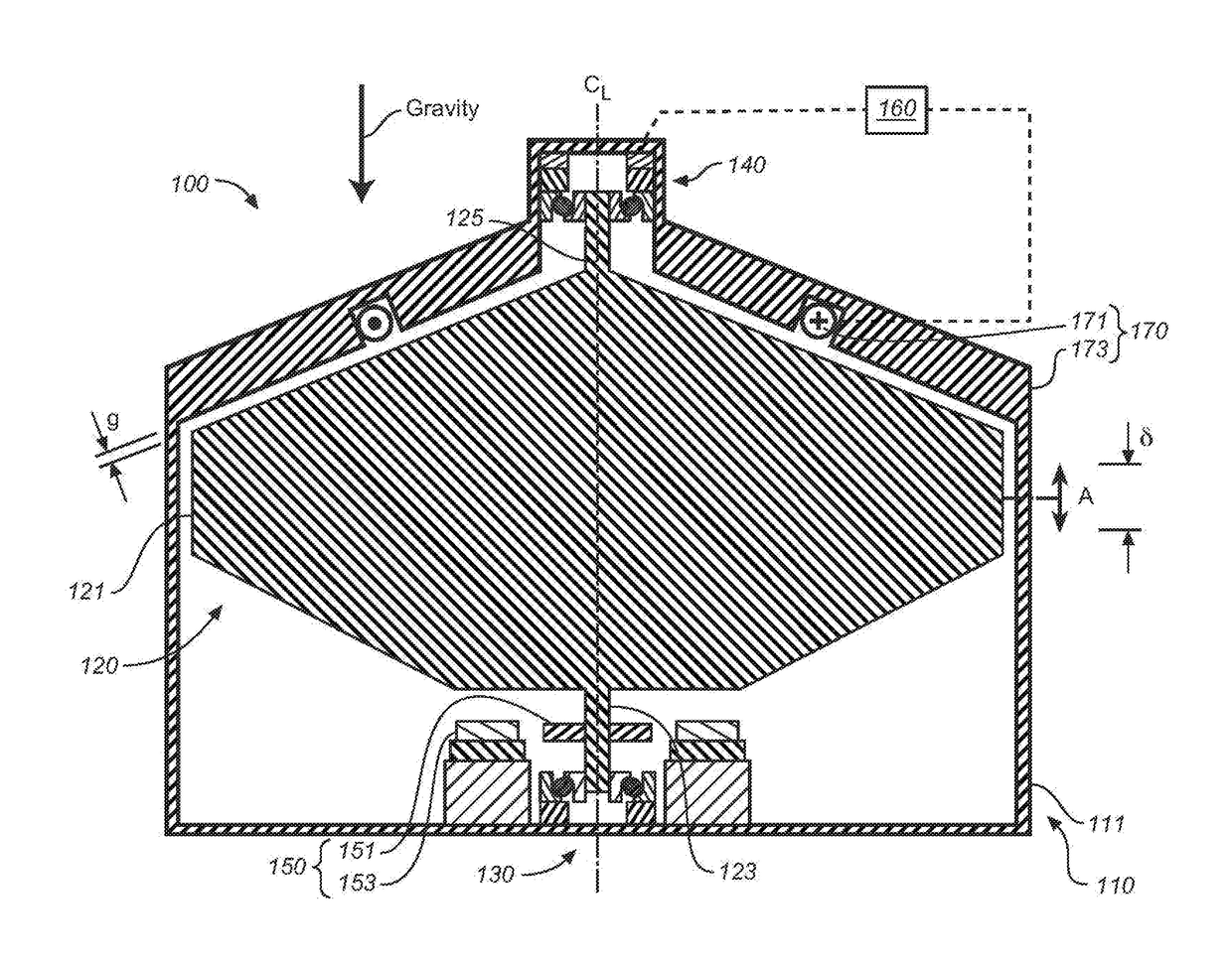
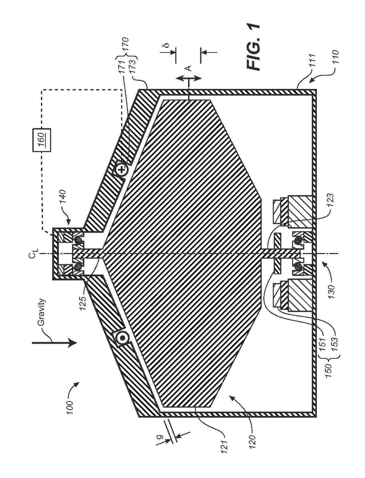
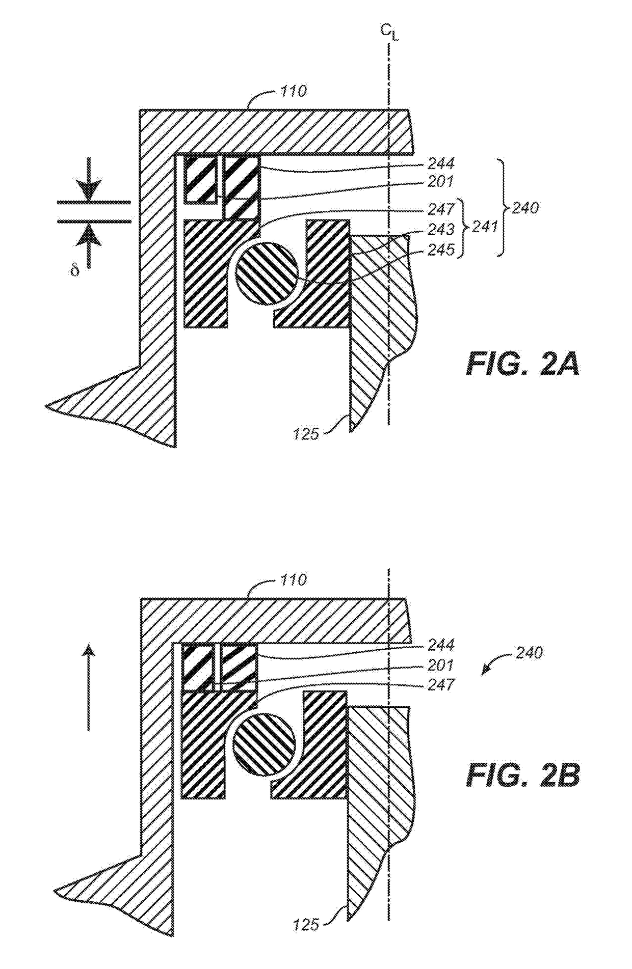
[0030]FIG. 1 is a schematic cross-sectional view of a first embodiment flywheel apparatus 100 which includes a housing 110, a rotor 120 having a rotational axis CL, and bearings for supporting the rotor and permitting rotation, and which may include a lower bearing assembly 130 and an upper bearing assembly 140. Flywheel apparatus 100 also includes a magnet 170; power components 150 for adding or removing power from rotor 120; and a magnetic offloading control system 160. Flywheel apparatus 100 and bearing assemblies 130 and 140 are generally symmetric about a centerline CL. As discussed subsequently, bearing assemblies 130 and 140 support rotor 120 while permitting some axial motion of the rotor, indicated by arrow A, and where the total range of axial motion is indicated as δ.

[0031]As discussed subsequently, magnet 170 includes an electro-magnet, which is also referred to herein without limitation, as an “offloader” or “offloader electromagnet,” which may be operated to provide a ...

second embodiment

[0073]The following discussion provides alternative embodiments for control of flywheel assembly 100 based on measurements related to the magnetic flux the produces force F. FIG. 9 is a schematic cross-sectional view of a second embodiment flywheel apparatus 900. Flywheel apparatus 900 is generally similar to flywheel apparatus 100, except as explicitly discussed subsequently.

[0074]Flywheel apparatus include a rotor 920 that is more cylindrically shaped than rotor 120, but is otherwise generally similar. Rotor 920 may be used in any of the previous embodiments, which may be for example and without limitation the embodiments of any one of FIG. 1, 2, 3, 6 or 7. Alternatively, the non-mechanical sensing and method of operation of this section may be incorporated into rotor 120, or rotors of other, different geometries.

[0075]Flywheel apparatus is also provided with one or more gap magnetic field sensing elements. FIG. 9 shows the placement of a first Hall sensor 901 which is located dir...

third embodiment

[0084]FIG. 13 is a schematic cross-sectional view of a flywheel apparatus 1300 of the present invention having a third embodiment magnet 1370. Flywheel apparatus 1300 is generally similar to any of the flywheel apparatus described above. Magnet 1370 includes magnet 170, which is an electromagnet, and a permanent magnet 1301. In this embodiment, magnet 1301 is an axially magnetized, axisymmetric ring magnet that is configured to be in series with the flux path of magnet 170.

[0085]As in flywheel apparatus 1200, rotor 920 of flywheel apparatus 1300 is lifted by the combination of and electromagnet and permanent magnet, and thus the windings of the electromagnet of magnet 1370 may be proportionally smaller than those of flywheel apparatus 100.

Flipped-Bearing Embodiments

[0086]FIG. 14 is a schematic cross-sectional view of a third embodiment of an upper bearing assembly 1440, referred to as a flipped-bearing embodiment, and FIG. 15 is a schematic cross-sectional view of a third embodiment...


PUM


Abstract

A flywheel apparatus that magnetically unloads a top rotor bearing is described. The apparatus includes a flywheel housing, a rotor with a vertical axis of rotation that includes a magnetic material, a magnet configured to apply a desired upward off-loading force along the vertical axis of rotation, an upper bearing connected to an upper shaft of the rotor, and a bearing housing disposed between the upper bearing and the flywheel housing that substantially prevents downward axial motion of the upper bearing. The magnet includes an electromagnet. A force sensor is used to measure a force on the upper bearing which is provided as input to a controller that updates the current to the electromagnet. The rotor is maintained in a fixed axial position and a spring disposed below a lower bearing absorbs axial dimension growth of the rotor.

Description

CROSS-REFERENCE TO RELATED APPLICATIONS[0001]This application is a continuation-in-part of U.S. application Ser. No. 13 / 973,937, filed Aug. 22, 2013 which claims the benefit of U.S. Provisional Application No. 61 / 692,631, filed Aug. 23, 2012, the disclosures of which are incorporated herein by reference in their entireties. This application is also a continuation-in-part of U.S. application Ser. No. 15 / 191,398 filed on Jun. 23, 2016 which claims benefit of U.S. Provisional Application No. 62 / 185,441 filed on Jun. 26, 2015, the disclosures of which are also incorporated herein by reference in their entireties.BACKGROUND OF THE INVENTIONField of the Invention[0002]The present invention generally relates to rotors supported by mechanical bearings, and more particularly to a method and apparatus for unloading the weight of the rotor from its bearings.Discussion of the Background[0003]Rotors, such as those used for storing rotational kinetic energy, have shafts along their axis of rotati...

Claims


Application Information

Patent Timeline
IPC IPC(8): F16F15/315H01F7/02F16C39/06
CPCF16F15/3156H01F7/0231F16C39/063F16C19/163F16C19/522F16C19/547F16C32/0408F16C32/0444F16C39/06F16C2361/55H02K7/025H02K7/083H02K7/09H02K7/02Y02E60/16
Inventor SANDERS, SETH R.TENNESSEN, PETER THOMASBAKHOLDIN, DANIELGARTEN, MATTHEW BRANDONHOLLOWAY, MARK J.SENESKY, MATTHEW K.
Owner AMBER KINETICS
Learn More