Apparatus and method for magnetically unloading a rotor bearing

a technology of rotor bearing and magnetic unloading, which is applied in the field of rotors, can solve the problems of large bearings, limited ball bearing lifetime, and roller bearings capable of supporting large weights are necessarily large and expensive, and achieve accurate prescribing of residual axial preload and avoid ball skidding

Active Publication Date: 2018-02-13
AMBER KINETICS
View PDF58 Cites 5 Cited by
  • Summary
  • Abstract
  • Description
  • Claims
  • Application Information

AI Technical Summary

Benefits of technology

[0009]The present invention overcomes the disadvantages of prior art rotor support apparatus and methods by unloading a large fraction of the weight supported by the bearings of a vertically mounted rotor. In one embodiment, the load on the bottom bearing is magnetically unloaded to a minimal preload setting as determined by an axial spring in series with the bottom bearing assembly. The preloading on the bottom bearing may be set to a desired and practical minimal value, thus avoiding ball skidding and any other drawbacks of a nearly unloaded bottom bearing. In one embodiment, this amount of preloading is accomplished by applying a magnetic lifting force that exceeds, by a small margin, the gravitational weight of the rotor. This small difference between magnetic lifting force and rotor weight constitutes the preload placed on the upper bearing. The present invention also comprises the mechanical system layout, and the controls needed to accurately prescribe the residual axial preload on the upper bearing.
[0010]Application of this level of magnetic force has three essential effects. First, loading on the bottom bearing can be entirely and precisely set with an axial spring. Second, with slip-fit mountings for the upper and bottom bearing outer rings (or raceways) in their respective bores, the rotor is lifted through a small axial clearance distance. This clearance is provided to allow for differential expansion of the rotor and housing under mismatched thermal conditions, and under Poisson effect induced rotor axial length variation due to centripetal loading. With the rotor fully lifted to a stopped position defined by the upper bearing assembly, the gap defining magnetic actuation forces is precisely set. As such, the magnetic lifting force of a prescribed winding current is very accurate and repeatable. Further, since the magnetic gap is at its minimal possible setting, the power required by a magnetic lifting winding is minimal. Third, an axial preloading force is imparted on the upper bearing. This preloading force is determined by the difference between the magnetic lifting force and the gravitational weight of the rotor.
[0018]Another embodiment includes a magnetic field sensing element, such as a Hall Effect sensor, to sense the offloading electromagnet flux density. As will be described, magnetic force scales very accurately with the square of the gap magnetic flux density. As such, the offloader electromagnet force can be precisely assessed by measurement of the gap magnetic flux density. This measured magnetic field quantity can be conveniently used in the offloader control to precisely set the axial preload force on the upper bearing.

Problems solved by technology

While the use of rolling bearings to support rotors is effective, the typical use of such bearings requires large bearings.
Roller bearings capable of supporting large weights are necessarily large and expensive.
In addition, as is known in the field, ball bearing lifetime is limited by raceway fatigue, and scales inversely with the cubic power of the bearing load.

Method used


Image

  • Apparatus and method for magnetically unloading a rotor bearing
  • Apparatus and method for magnetically unloading a rotor bearing
  • Apparatus and method for magnetically unloading a rotor bearing

Examples


first embodiment

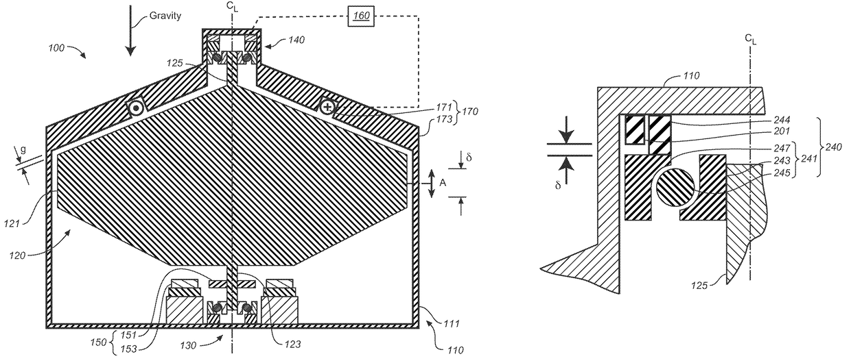
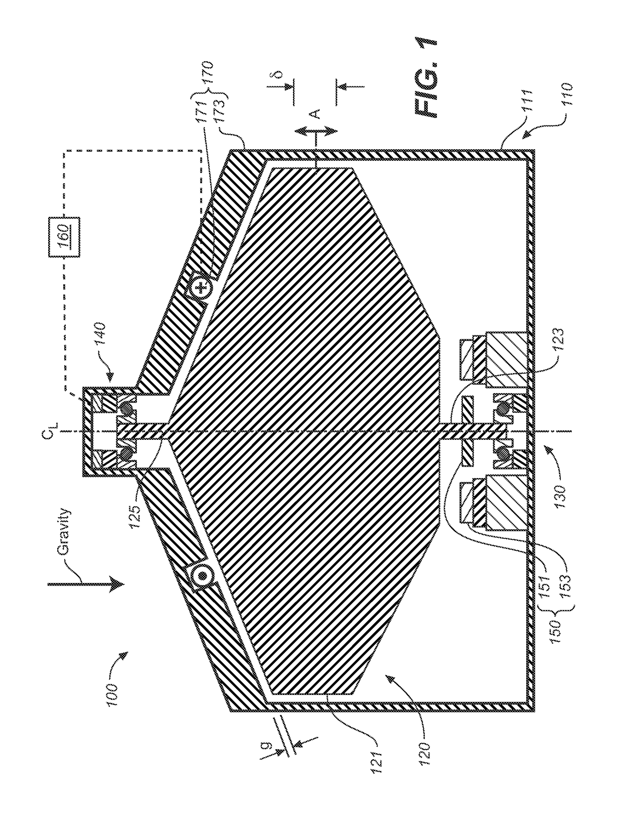
[0036]FIG. 1 is a schematic cross-sectional view of a first embodiment flywheel apparatus 100 which includes a housing 110, a rotor 120 having a rotational axis CL, and bearings for supporting the rotor and permitting rotation, and which may include a lower bearing assembly 130 and an upper bearing assembly 140. Flywheel apparatus 100 also includes a magnet 170; power components 150 for adding or removing power from rotor 120; and a control system 160. Flywheel apparatus 100 and bearing assemblies 130 and 140 are generally symmetric about a centerline CL. As discussed subsequently, bearing assemblies 130 and 140 support rotor 120 while permitting some axial motion of the rotor, indicated by arrow A, and where the total range of axial motion is indicated as δ.

[0037]As discussed subsequently, magnet 170 includes an electro-magnet, which is also referred to herein without limitation, as an “offloader” or “offloader electromagnet,” which may be operated to provide a force on rotor 120 t...

second embodiment

[0079]The following discussion provides alternative embodiments for control of flywheel assembly 100 based on measurements related to the magnetic flux the produces force F. FIG. 9 is a schematic cross-sectional of a second embodiment flywheel apparatus 900. Flywheel apparatus 900 is generally similar to flywheel apparatus 100, except as explicitly discussed subsequently.

[0080]Flywheel apparatus include a rotor 920 that is more cylindrically shaped than rotor 120, but is otherwise generally similar. Rotor 920 may be used in any of the previous embodiments, which may be for example and without limitation the embodiments of any one of FIG. 1, 2, 3, 6 or 7. Alternatively, the non-mechanical sensing and method of operation of this section may be incorporated into rotor 120, or rotors of other, different geometries.

[0081]Flywheel apparatus is also provided with one or more gap magnetic field sensing elements. FIG. 9 shows the placement of a first Hall sensor 901 which is located directly...

third embodiment

[0090]FIG. 13 is a schematic cross-sectional of a flywheel apparatus 1300 of the present invention having a third embodiment magnet 1370. Flywheel apparatus 1300 is generally similar to any of the flywheel apparatus described above. Magnet 1370 includes magnet 170, which is an electromagnet, and a permanent magnet 1301. In this embodiment, magnet 1301 is an axially magnetized, axisymmetric ring magnet that is configured to be in series with the flux path of magnet 170.

[0091]As in flywheel apparatus 1200, rotor 920 of flywheel apparatus 1300 is lifted by the combination of and electromagnet and permanent magnet, and thus the windings of the electromagnet of magnet 1370 may be proportionally smaller than those of flywheel apparatus 100.

[0092]One embodiment of each of the methods described herein is in the form of a computer program that executes on a processing system, e.g., a one or more processors that are part of a control system. Thus, as will be appreciated by those skilled in th...


PUM

PropertyMeasurementUnit
weightaaaaaaaaaa
weightaaaaaaaaaa
weightaaaaaaaaaa

Abstract

An apparatus and method for unloading a rotor bearing is described. The apparatus includes an electromagnet for levitating the rotor. In one embodiment, a sensor of the magnetic field near the electromagnet is used to control the current to levitate the rotor. In another embodiment, a method is provided that includes rotating the rotor, increasing the current to levitate the rotor and decrease the gap between electromagnet and rotor, and then reducing the current to levitate the rotor with a minimal amount of electric power to the electromagnet.

Description

CROSS-REFERENCE TO RELATED APPLICATIONS[0001]This application claims the benefit of U.S. Provisional Application No. 61 / 692,631, filed Aug. 23, 2013, the disclosure of which is incorporated herein by reference in its entirety.STATEMENT REGARDING FEDERALLY SPONSORED RESEARCH OR DEVELOPMENT[0002]This invention was made with government support under DE-FOA-0000036 awarded by the U.S. Department of Energy. The government has certain rights in the invention.BACKGROUND OF THE INVENTION[0003]Field of the Invention[0004]The present invention generally relates to rotors supported by mechanical bearings, and more particularly to a method and apparatus for unloading the weight of the rotor from its bearings.[0005]Discussion of the Background[0006]Rotors, such as those used for storing rotational kinetic energy, have shafts along their axis of rotation that are typically supported by rolling bearings. Thus, for example, a vertically oriented rotor may have a lower rolling bearing and an upper r...

Claims


Application Information

Patent Timeline
Patent Type & Authority Patents(United States)
IPC IPC(8): H02K7/02H02K7/09F16C32/04F16C39/06H01F7/20F16C19/52F16C19/54H01F7/02F16C19/16
CPCH01F7/206F16C19/547F16C32/0444F16C39/06H02K7/02H02K7/025F16C19/522H02K7/09F16C19/163F16C32/044F16C32/0406F16C32/0451F16C32/0459F16C2361/55H01F7/0236Y02E60/16F16C32/04
Inventor SANDERS, SETH ROBERT
Owner AMBER KINETICS
Why Eureka
Try Eureka