Apparatus and method for magnetically unloading a rotor bearing
- Summary
- Abstract
- Description
- Claims
- Application Information
AI Technical Summary
Benefits of technology
Problems solved by technology
Method used
Image
Examples
first embodiment
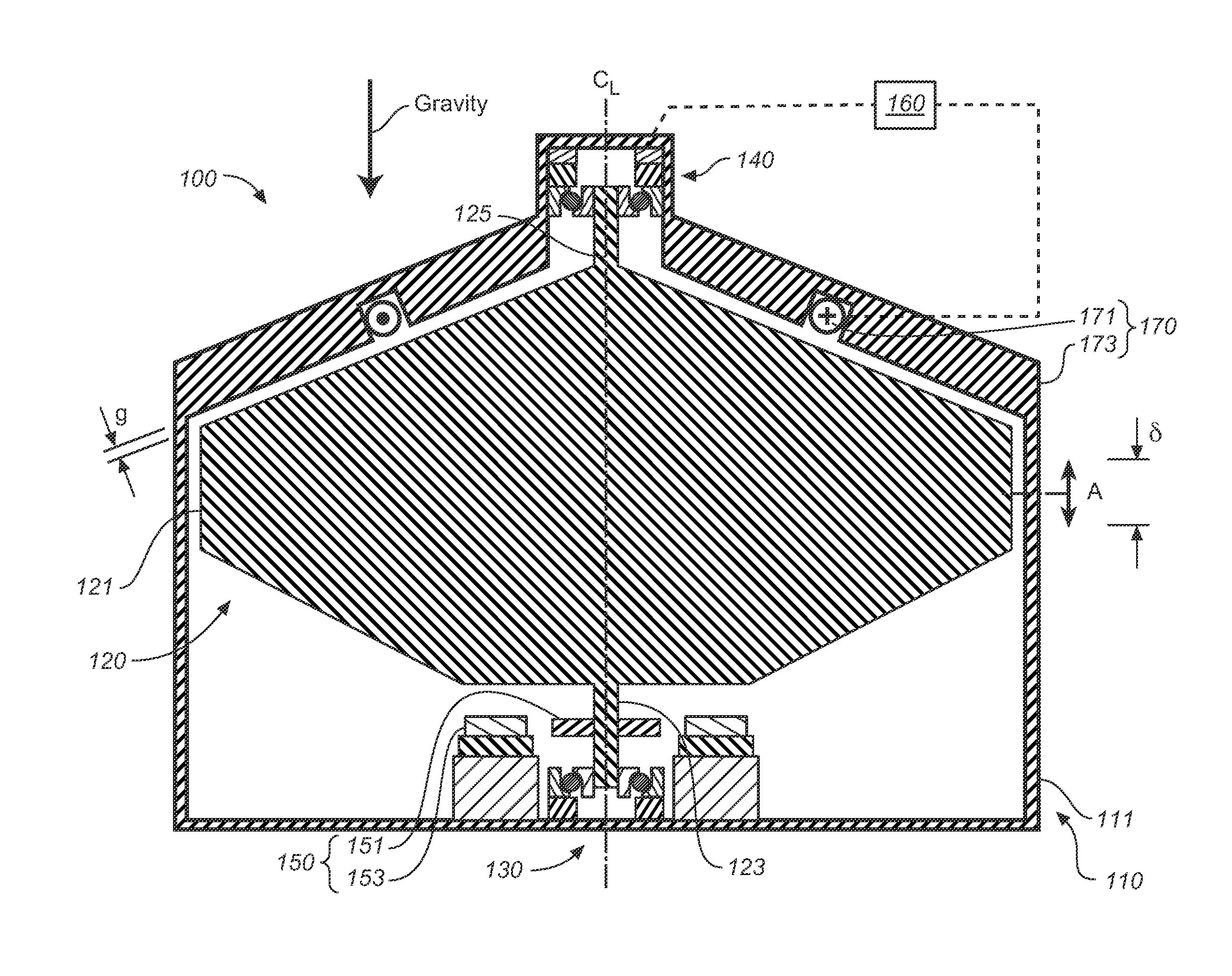
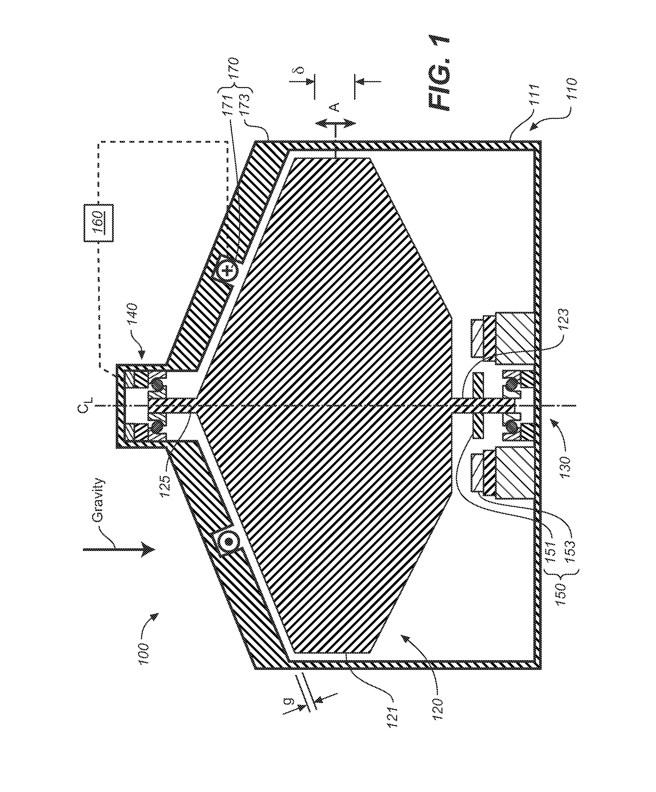
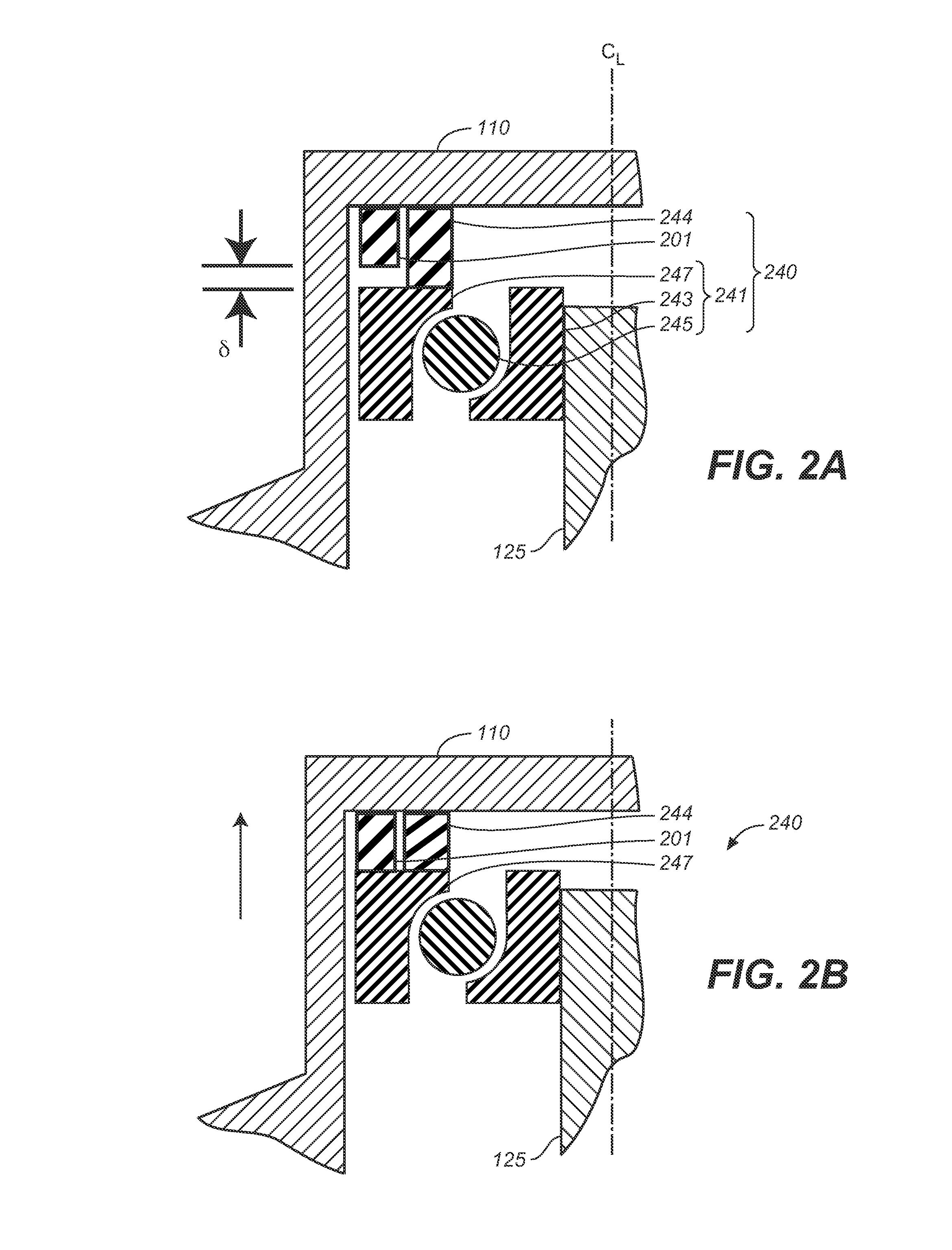
[0036]FIG. 1 is a schematic cross-sectional view of a first embodiment flywheel apparatus 100 which includes a housing 110, a rotor 120 having a rotational axis CL, and bearings for supporting the rotor and permitting rotation, and which may include a lower bearing assembly 130 and an upper bearing assembly 140. Flywheel apparatus 100 also includes a magnet 170; power components 150 for adding or removing power from rotor 120; and a control system 160. Flywheel apparatus 100 and bearing assemblies 130 and 140 are generally symmetric about a centerline CL. As discussed subsequently, bearing assemblies 130 and 140 support rotor 120 while permitting some axial motion of the rotor, indicated by arrow A, and where the total range of axial motion is indicated as δ.
[0037]As discussed subsequently, magnet 170 includes an electro-magnet, which is also referred to herein without limitation, as an “offloader” or “offloader electromagnet,” which may be operated to provide a force on rotor 120 t...
second embodiment
[0079]The following discussion provides alternative embodiments for control of flywheel assembly 100 based on measurements related to the magnetic flux the produces force F. FIG. 9 is a schematic cross-sectional of a second embodiment flywheel apparatus 900. Flywheel apparatus 900 is generally similar to flywheel apparatus 100, except as explicitly discussed subsequently.
[0080]Flywheel apparatus include a rotor 920 that is more cylindrically shaped than rotor 120, but is otherwise generally similar. Rotor 920 may be used in any of the previous embodiments, which may be for example and without limitation the embodiments of any one of FIG. 1, 2, 3, 6 or 7. Alternatively, the non-mechanical sensing and method of operation of this section may be incorporated into rotor 120, or rotors of other, different geometries.
[0081]Flywheel apparatus is also provided with one or more gap magnetic field sensing elements. FIG. 9 shows the placement of a first Hall sensor 901 which is located directly...
third embodiment
[0090]FIG. 13 is a schematic cross-sectional of a flywheel apparatus 1300 of the present invention having a third embodiment magnet 1370. Flywheel apparatus 1300 is generally similar to any of the flywheel apparatus described above. Magnet 1370 includes magnet 170, which is an electromagnet, and a permanent magnet 1301. In this embodiment, magnet 1301 is an axially magnetized, axisymmetric ring magnet that is configured to be in series with the flux path of magnet 170.
[0091]As in flywheel apparatus 1200, rotor 920 of flywheel apparatus 1300 is lifted by the combination of and electromagnet and permanent magnet, and thus the windings of the electromagnet of magnet 1370 may be proportionally smaller than those of flywheel apparatus 100.
[0092]One embodiment of each of the methods described herein is in the form of a computer program that executes on a processing system, e.g., a one or more processors that are part of a control system. Thus, as will be appreciated by those skilled in th...
PUM
 Abstract
Description
Claims
Application Information
 - R&D
- Intellectual Property
- Life Sciences
- Materials
- Tech Scout
- Unparalleled Data Quality
- Higher Quality Content
- 60% Fewer Hallucinations
Browse by: Latest US Patents, China's latest patents, Technical Efficacy Thesaurus, Application Domain, Technology Topic, Popular Technical Reports.
© 2025 PatSnap. All rights reserved.Legal|Privacy policy|Modern Slavery Act Transparency Statement|Sitemap|About US| Contact US: help@patsnap.com


