
Calibrating a thermal scanning system

a thermal scanning and calibration method technology, applied in the field of thermal scanning system calibration, can solve the problems of lack of objective measurement basis to alter the calibration value, the probability of data collection from patients using sensors that have not been recently calibrated, and the inability to perform calibration procedures accurately and repeatably, so as to improve the thermal scanning calibration protocol and calculation, the effect of eliminating the possibility of performing a calibration procedur

Inactive Publication Date: 2008-10-21
GENTEMPO JR PATRICK +1
View PDF6 Cites 2 Cited by
  • Summary
  • Abstract
  • Description
  • Claims
  • Application Information

AI Technical Summary

Benefits of technology

This approach provides a more accurate and repeatable calibration process, ensuring that patient data is collected with properly calibrated sensors, reducing errors and the complexity of calibration procedures.

Problems solved by technology

This is often not the case in practice, however, as the calibration of each of the thermal sensors can drift over time or be influenced by environmental conditions such as operating temperature and humidity.
Disadvantages of this technique include: (1) potential error in having the user point each sensor at a spot with a stable temperature reading, and (2) potentially collecting data from patients using sensors that are not calibrated.
Disadvantages of this technique include: (1) lack of an objective measurement basis to alter the calibration values, and (2) the likelihood of data collection from patients using sensors that have not been recently calibrated.

Method used


Image

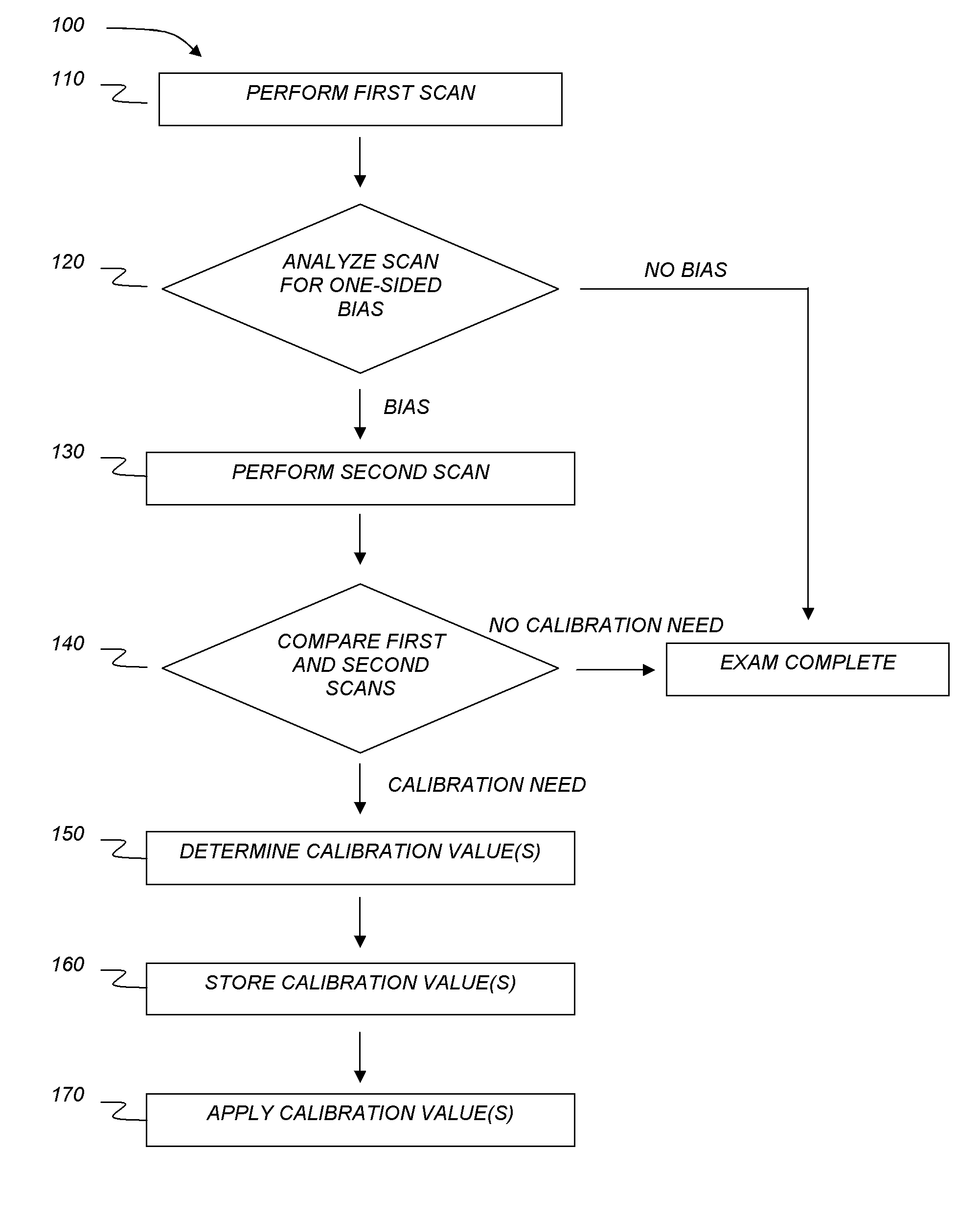
  • Calibrating a thermal scanning system
  • Calibrating a thermal scanning system
  • Calibrating a thermal scanning system

Examples


example

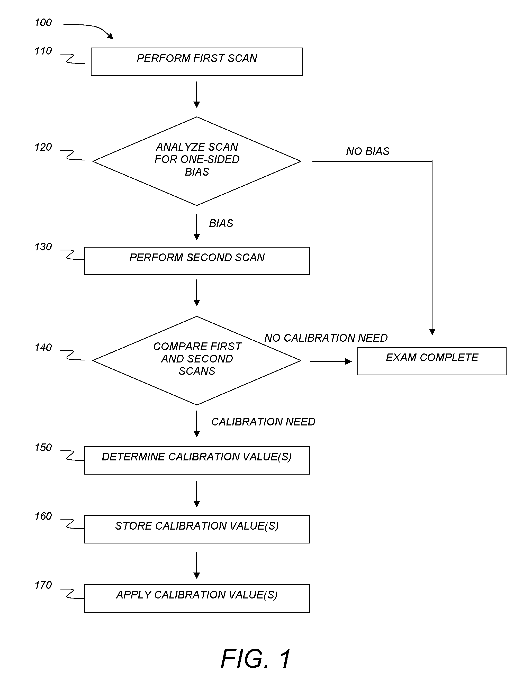
[0049]The following example describes a particular embodiment of a method for calibrating an Insight Millennium Rolling Thermal Scanner. Those skilled in the art will understand that other embodiments use other calibration methods and / or devices.

[0050]The Rolling Thermal Scanner is rolled up the spine in an upward scan, collecting a first set of thermal scanning data. As the scanner rolls up the spine, an UpLeftAvgTemp (average temperature of the left thermal sensor on the upward scan) and an UpRightAvgTemp (average temperature of the right thermal sensor on the upward scan) values are also calculated. For each thermal sensor, these values are rolling averages of (Temp−CaseTemp) for each data point except the C1 values, where “Temp” is the temperature recorded by a thermal sensor and “CaseTemp” is the temperature of the rolling scanner. The Rolling Thermal Scanner is equipped with a thermal sensor that reports the temperature of the scanner itself (CaseTemp), which permits the conve...


PUM

PropertyMeasurementUnit
temperature biasaaaaaaaaaa
temperatureaaaaaaaaaa

Abstract

A method for recalibrating a bilateral thermal scanner comprising a first thermal sensor and a second thermal sensor can comprise acquiring a first set of thermal scanning data with the thermal sensors in their normal positions; optionally analyzing the first set of thermal scanning data is analyzed to determine if the data has a one-sided bias; acquiring a second set of thermal scanning data with the positions of the thermal sensors reversed; determining a calibration from the first and second sets of thermal scanning data; and optionally correcting at least one of the first and / or second set of thermal scanning data using the calibration.

Description

CROSS-REFERENCE TO RELATED APPLICATIONS[0001]This application claims the benefit of U.S. Application No. 60 / 753,109, filed Dec. 22, 2005, the disclosure of which is incorporated by reference.BACKGROUND[0002]1. Technical Field[0003]This disclosure generally relates to a method for calibrating medical diagnostic equipment, and more particularly, to a method for calibrating a thermal scanning system.[0004]2. Description of the Related Art[0005]Chiropractors and other health care professionals currently use devices to measure skin temperature at a variety of locations along a patient's spinal column. The purpose of taking such measurements is to monitor skin temperatures surrounding the spine. Imbalances in bilateral skin temperature readings may be indicative of abnormal autonomous nervous system activity, which in turn may indicate a spinal subluxation, or misalignment of adjacent vertebrae. Chiropractic care is directed toward locating and correcting subluxations by spinal adjustment...

Claims


Application Information

Patent Timeline
Patent Type & Authority Patents(United States)
IPC IPC(8): G01K15/00A61B5/00G01K3/00G01J5/00G01K13/00
CPCA61B5/015G01J5/0022G01J5/0025A61B2560/0223G01J2005/0048G01J2005/0081G01J5/48G01J5/80
Inventor GENTEMPO, JR., PATRICKBRODY, LEE L
Owner GENTEMPO JR PATRICK
Learn More