Low-power high-intensity lighting apparatus

a lighting apparatus and high-intensity technology, applied in the field of low-power high-intensity lighting apparatus, can solve the problems of poor productivity, higher cost, and relatively complicated process of lighting and heating apparatus, and achieve the effect of easy assembly and few parts

Inactive Publication Date: 2006-06-06
LEDIQ
View PDF9 Cites 62 Cited by
  • Summary
  • Abstract
  • Description
  • Claims
  • Application Information

AI Technical Summary

Benefits of technology

[0008]Therefore, the object of the present invention is to provide a low-power high-intensity lighting apparatus that includes few parts and that is easy to assemble.

Problems solved by technology

Therefore, the assembly process thereof is relatively complicated, and results in poor productivity and higher costs.

Method used


Image

  • Low-power high-intensity lighting apparatus
  • Low-power high-intensity lighting apparatus
  • Low-power high-intensity lighting apparatus

Examples


Embodiment Construction

[0018]Before the present invention is described in greater detail, it should be noted that like elements are denoted by the same reference numerals throughout the disclosure.

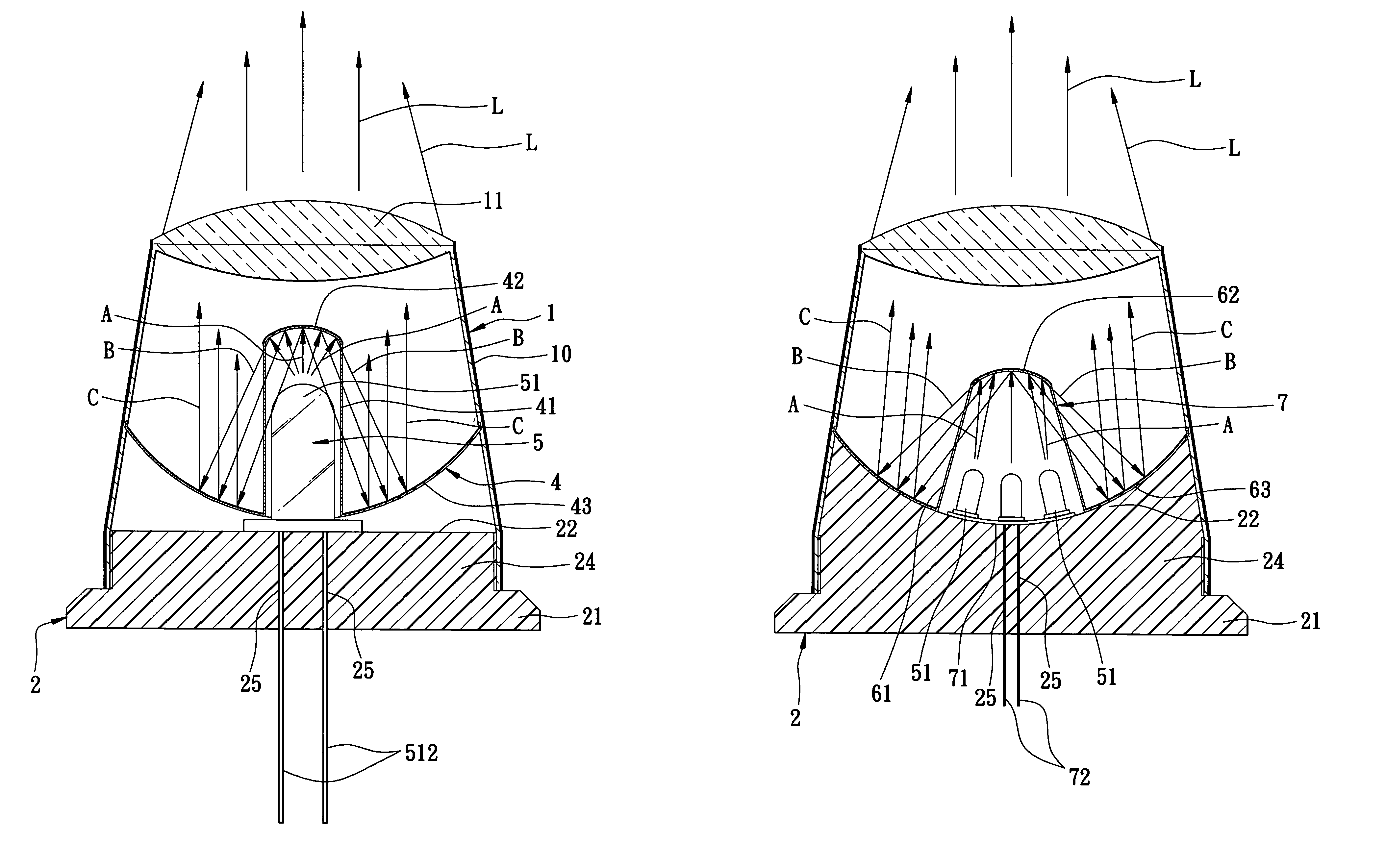
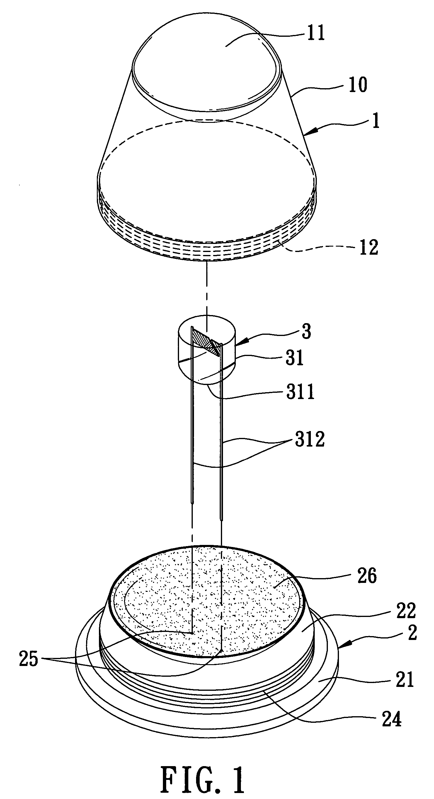
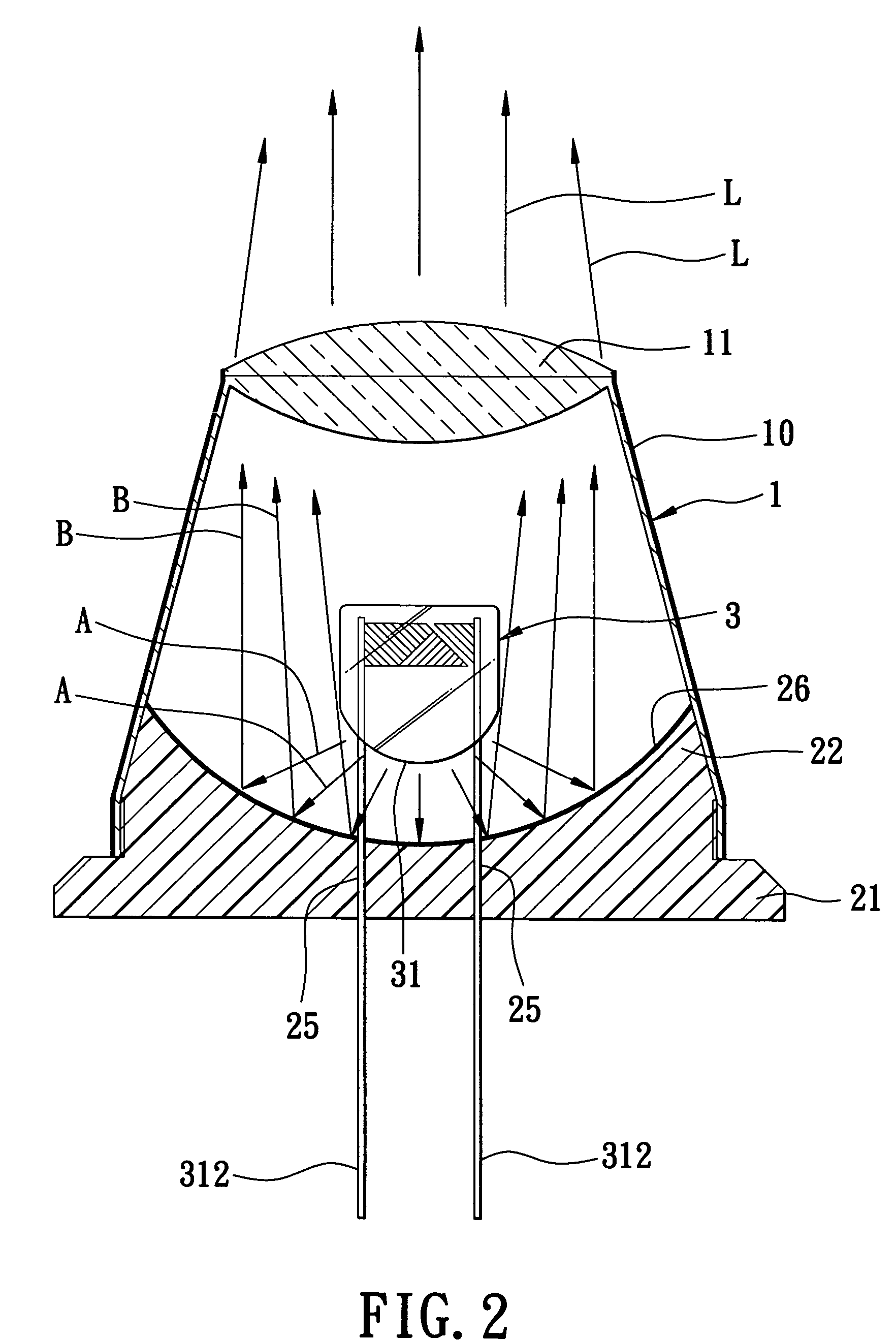
[0019]Referring to FIGS. 1 and 2, the first preferred embodiment of a low-power high-intensity lighting apparatus according to this invention is shown to include a lamp base 2, a lamp housing 1, and a lamp unit 3.

[0020]The lamp base 2 has a base part 21, a mounting part 22 opposite to the base part 21, and a peripheral part 24 that interconnects the base and mounting parts 21, 22. In this embodiment, the lamp base 2 includes a parabolic reflector 26 that is formed at the mounting part 22. The peripheral part 24 of the lamp base 2 is formed with an outer thread. The lamp base 2 is further formed with a pair of terminal holes 25 that extend through the parabolic reflector 26.

[0021]The lamp housing 1 is mounted on the lamp base 2. In this embodiment, the lamp housing 1 includes a surrounding wall 10 and an optical ...


PUM


Abstract

A low-power high-intensity lighting apparatus includes a lamp base, a lamp housing, and a lamp unit. The lamp base includes a parabolic reflector. The lamp housing is mounted on the lamp base, and includes a surrounding wall and an optical condenser. The surrounding wall has a first open end, and a second open end opposite to the first open end. The optical condenser is mounted on the lamp housing at the second open end. The lamp unit is mounted on the lamp base, extends into the lamp housing through the first open end of the surrounding wall, and generates light that propagates toward the parabolic reflector and that is reflected by the parabolic reflector toward the optical condenser.

Description

CROSS-REFERENCE TO RELATED APPLICATION[0001]This application claims priority of Taiwanese application no. 093101619, filed on Jan. 20, 2004.BACKGROUND OF THE INVENTION[0002]1. Field of the Invention[0003]The invention relates to a lighting apparatus, more particularly to a low-power high-intensity lighting apparatus that includes few parts and that is easy to assemble.[0004]2. Description of the Related Art[0005]In U.S. Pat. No. 6,652,122, there is disclosed a conventional low-power high-intensity lighting apparatus that includes a housing, a lamp base, and a lamp unit. The housing includes a curved reflector. The lamp base includes a coupling post and a cap. The coupling post has an end that engages the reflector. The cap defines a diode-receiving cavity, and has an end that engages the coupling post. The lamp unit includes a light-emitting diode that is disposed in the diode-receiving cavity.[0006]In use, when power is supplied to the lamp unit, the light-emitting diode generates ...

Claims


Application Information

Patent Timeline
Patent Type & Authority Patents(United States)
IPC IPC(8): F21V3/00F21K99/00F21V7/00F21V13/04
CPCF21K99/00F21V7/0008F21Y2111/002F21Y2101/02F21V13/04F21S6/00F21Y2115/10
Inventor LIN, CHAO-TANG
Owner LEDIQ
Why Eureka
Try Eureka