
Method and apparatus for controlling driving current of illumination source in a display system

a technology of driving current and illumination source, which is applied in the direction of electric variable regulation, process and machine control, instruments, etc., can solve the problems of adversely affecting the brightness of the leds in the illumination source module 104/b>

Inactive Publication Date: 2006-06-06
AU OPTRONICS CORP +1
View PDF6 Cites 150 Cited by
  • Summary
  • Abstract
  • Description
  • Claims
  • Application Information

AI Technical Summary

Benefits of technology

"The present patent describes a system and method for providing a regulated driving current for an illumination source, such as a backlight source used in an LCD system. The system uses a current regulator to adjust the operating driving current for the illumination source based on a predetermined reference driving current and a corresponding electrical parameter. The current regulator provides a substantially constant operating driving current to the illumination source under various environmental and operating conditions. The technical effect of this patent is to provide a more efficient and effective way to drive the illumination source, ensuring consistent performance and reliability."

Problems solved by technology

As a result, the brightness of the LEDs in the illumination source module 104 can be adversely affected.

Method used


Image

  • Method and apparatus for controlling driving current of illumination source in a display system
  • Method and apparatus for controlling driving current of illumination source in a display system
  • Method and apparatus for controlling driving current of illumination source in a display system

Examples


Embodiment Construction

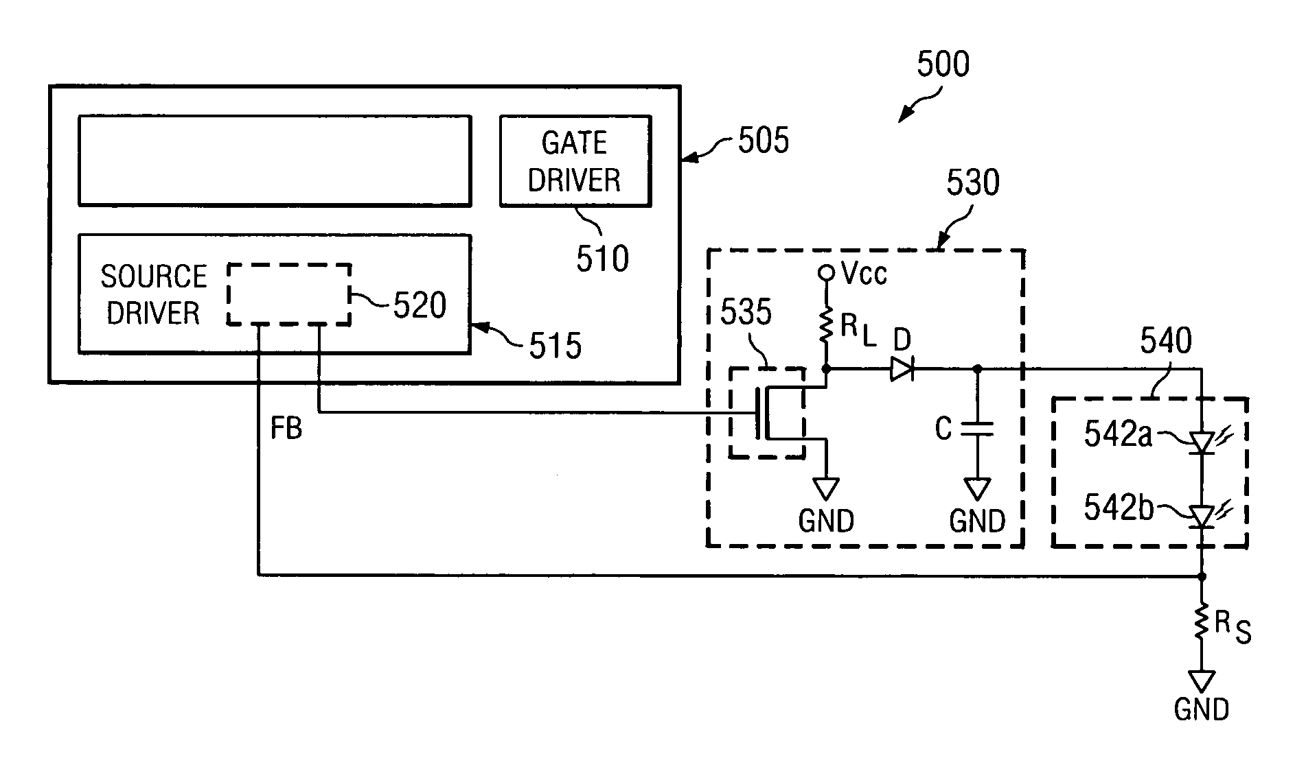
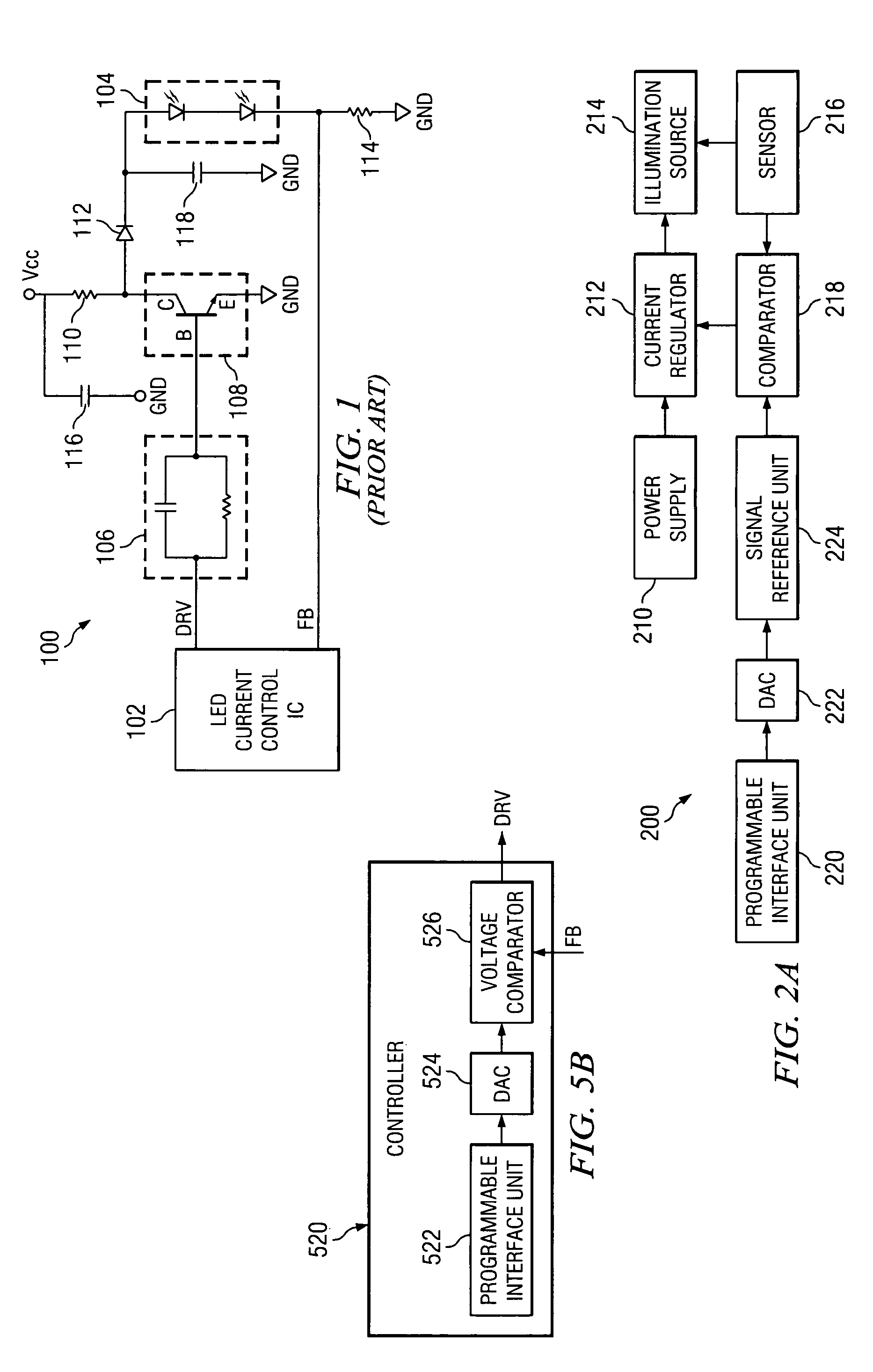
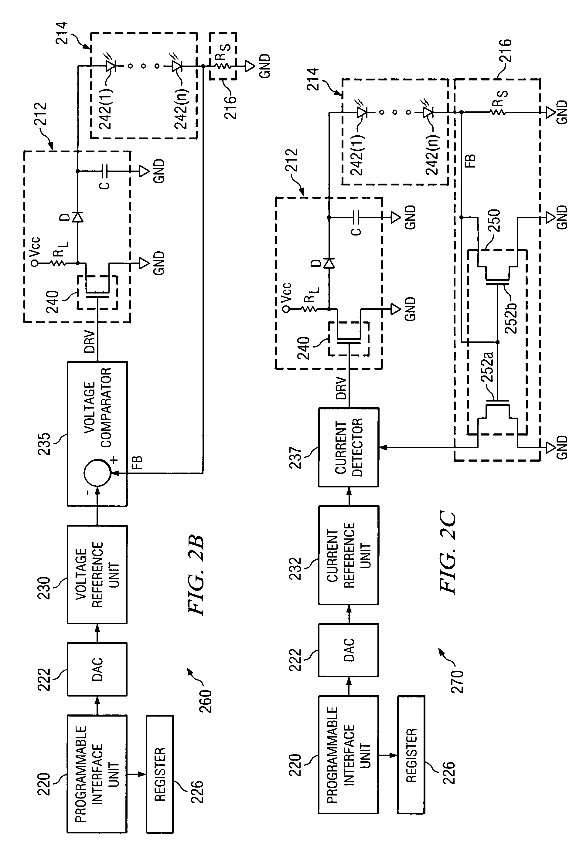
[0018]FIG. 2A is an exemplary block diagram illustrating a controller 200 configured to provide programmable regulated driving current for an illumination source 214. The controller 200 includes a power supply 210 configured to provide driving current for the illumination source 214. The illumination source 214 can include a backlight source used in a LCD system such as, a LED backlight source used in a small LCD system. A current regulator 212 is coupled to the power supply 210 and the illumination source 214. The current regulator 212 is configured to provide a regulated driving current for the illumination source 214. The current regulator 212 can be a transistor, such as a metal-oxide semiconductor transistor. A current sensor 216 is coupled to the illumination source 214. The current sensor 216 is configured to measure the driving current flowing through the illumination source 214.

[0019]A comparator 218 is coupled to the current sensor 216. The comparator 218 is also coupled t...


PUM

PropertyMeasurementUnit
electrical parameteraaaaaaaaaa
electrical parametersaaaaaaaaaa
programmable currentaaaaaaaaaa

Abstract

The present application describes a programmable current controller for regulating an operating driving current flowing through an illumination source. The driving current is regulated according to a digital reference corresponding to a predetermined operating current for the illumination source. The digital reference can be converted into a reference electrical parameter (current or voltage). The reference electrical parameter is compared with an operating electrical parameter (current or voltage) corresponding to the operating driving current of the illumination source. Based on the comparison, a driving bias current is generated, which is used to regulate the operating driving current of the illumination source.

Description

FIELD OF THE INVENTION[0001]The present invention relates generally to current regulators and, more particularly, to a programmable current regulator for an illumination source in a liquid crystal display system.DESCRIPTION OF THE RELATED ART[0002]Generally, Liquid Crystal Display (“LCD”) devices are used in various applications such as laptop computers, cellular phones, personal digital assistants, control panels of vehicles, and the like. Typically, an illumination source is placed behind a light modulator, such as a liquid crystal layer, in an LCD device to facilitate image visualization and produce optimal illumination. The illumination source can be a fluorescent lamp, an electroluminescent device, a light-emitting diode (LED), a gaseous discharge lamp, or the like. Typically, a control circuit provides regulated current to the illumination source.[0003]FIG. 1 illustrates a prior art implementation of a current regulator 100 for an illumination source module 104. The illuminati...

Claims


Application Information

Patent Timeline
Patent Type & Authority Patents(United States)
IPC IPC(8): G09G3/36G02F1/133G09G3/20G09G3/34H05B37/02H05B44/00
CPCH05B33/0842H05B37/0254H05B33/0851H05B45/10H05B47/18H05B45/345H05B31/50
Inventor HUNG, GHI-MAOLO, I-HSIN
Owner AU OPTRONICS CORP
Learn More