

Fixing apparatus and image forming apparatus
a technology of fixing apparatus and fixing plate, which is applied in the direction of electrographic process apparatus, instruments, optics, etc., can solve the problems that the heat emanating from the center coil for the time that is the difference between the desired warming-up operation period and the actual warming-up operation period is inevitably wasted, so as to shorten the time for warming up the heat roller and reduce the heat wasted during the warming-up operation period.
- Summary
- Abstract
- Description
- Claims
- Application Information
AI Technical Summary
Benefits of technology
Problems solved by technology
Method used
Image

Examples
first embodiment
[1] this invention will be described, with reference to some of the accompanying drawings.
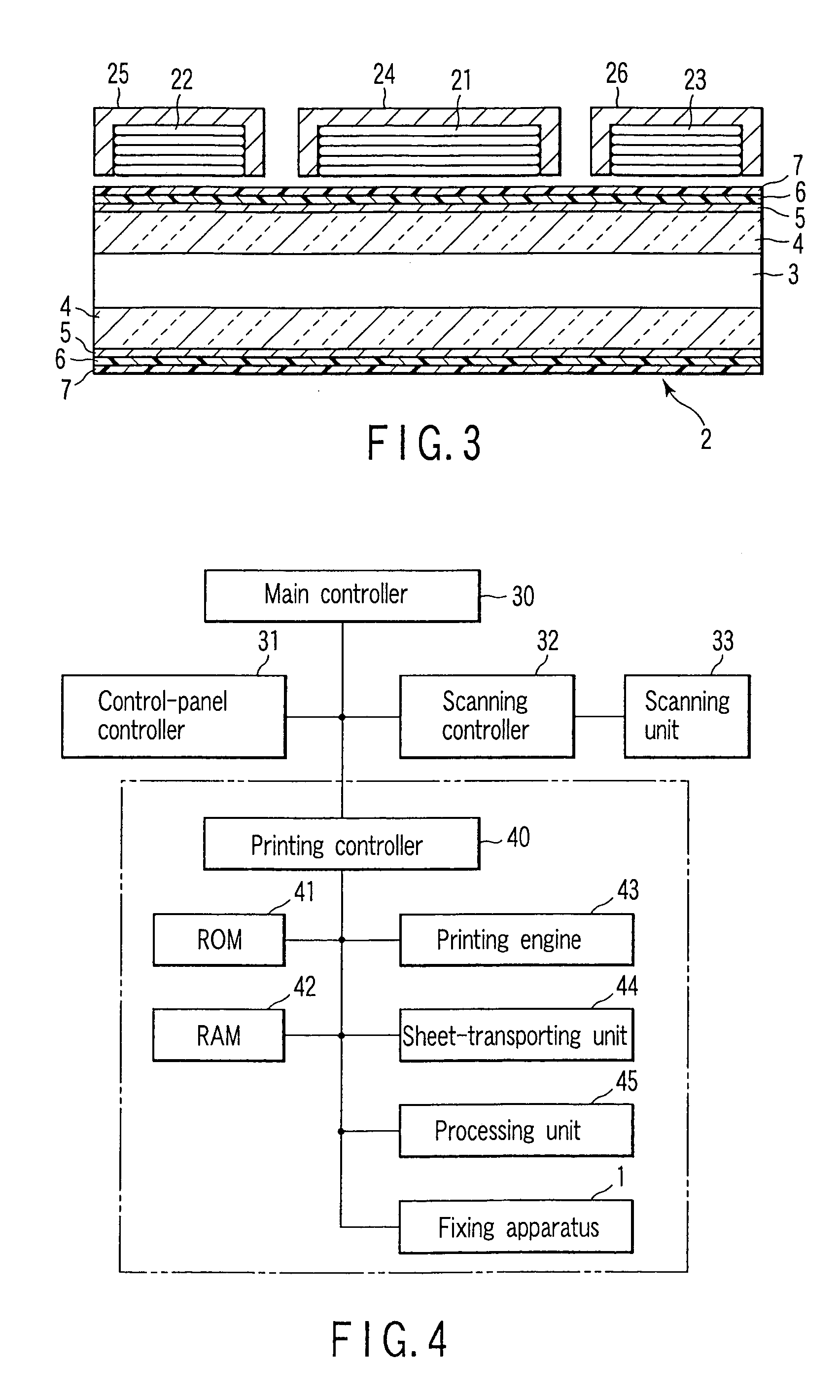
[0028]An image forming apparatus according to the first embodiment of the invention comprises a scanning unit (i.e., scanning unit 33 described later), a processing unit (i.e., processing unit 45 later described), and a fixing apparatus (i.e., fixing apparatus 1 described later). The scanning unit optically reads the image printed on an original document. The processing unit forms, on a paper sheet, a developer image corresponding to the image read by the scanning unit. The fixing apparatus heats the paper sheet, thereby fixing the developer image on the paper sheet. The image forming apparatus is configured as is disclosed in patent application Ser. No. 09 / 955,089, and its configuration will not be described herein.
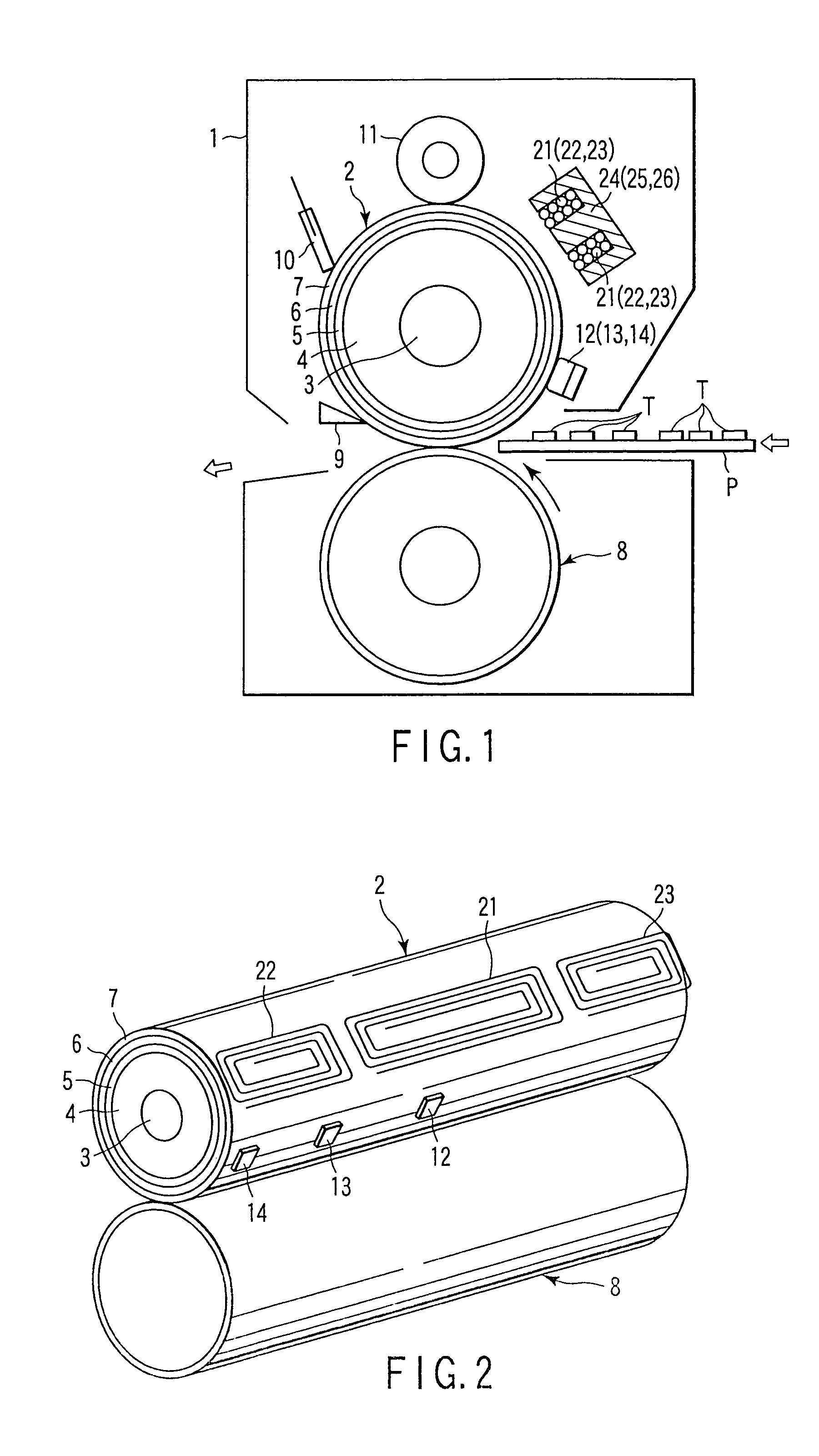
[0029]The fixing apparatus has the configuration illustrated in FIGS. 1, 2 and 3.
[0030]The fixing apparatus 1 has a rotary heating member such as a heat roller 2. The heat roller 2 ...
second embodiment
[2] this invention will be described.
[0056]FIG. 9 shows the various operating modes that are stored in the ROM 41.
[0057]In the standard mode “17” i.e., one of these operating modes, the center coil is driven for 1 second and the side coils 22 and 23 are driven for 1 second, too (drive-time ratio is 10:10). When the temperature rise ΔT1 is greater than the temperature rise ΔT2 as shown in FIG. 8, one of the operating modes “18”“19”“20”“21” and “22” is selected to increase the temperature rise ΔT2. In the operating mode “18” the center coil 21 is driven for 0.9 seconds and the side coils 22 and 23 are driven for 1.1 seconds (drive-time ratio is 9:11). In the operating mode “19” the center coil 21 is driven for 0.8 seconds and the side coils 22 and 23 are driven for 1.2 seconds (drive-time ratio is 8:12). In the operating mode “20” the center coil 21 is driven for 0.7 seconds and the side coils 22 and 23 are driven for 1.3 seconds (drive-time ratio is 7:13). In the operating mode “21” ...
third embodiment
[3] this invention will be described.
[0060]In this embodiment, the center coil 21 and the side coils 22 and 23 are driven at the same time, generating different amounts of output that are stored already, thus performing the warming-up operation. No limits are imposed on the sum of their outputs.
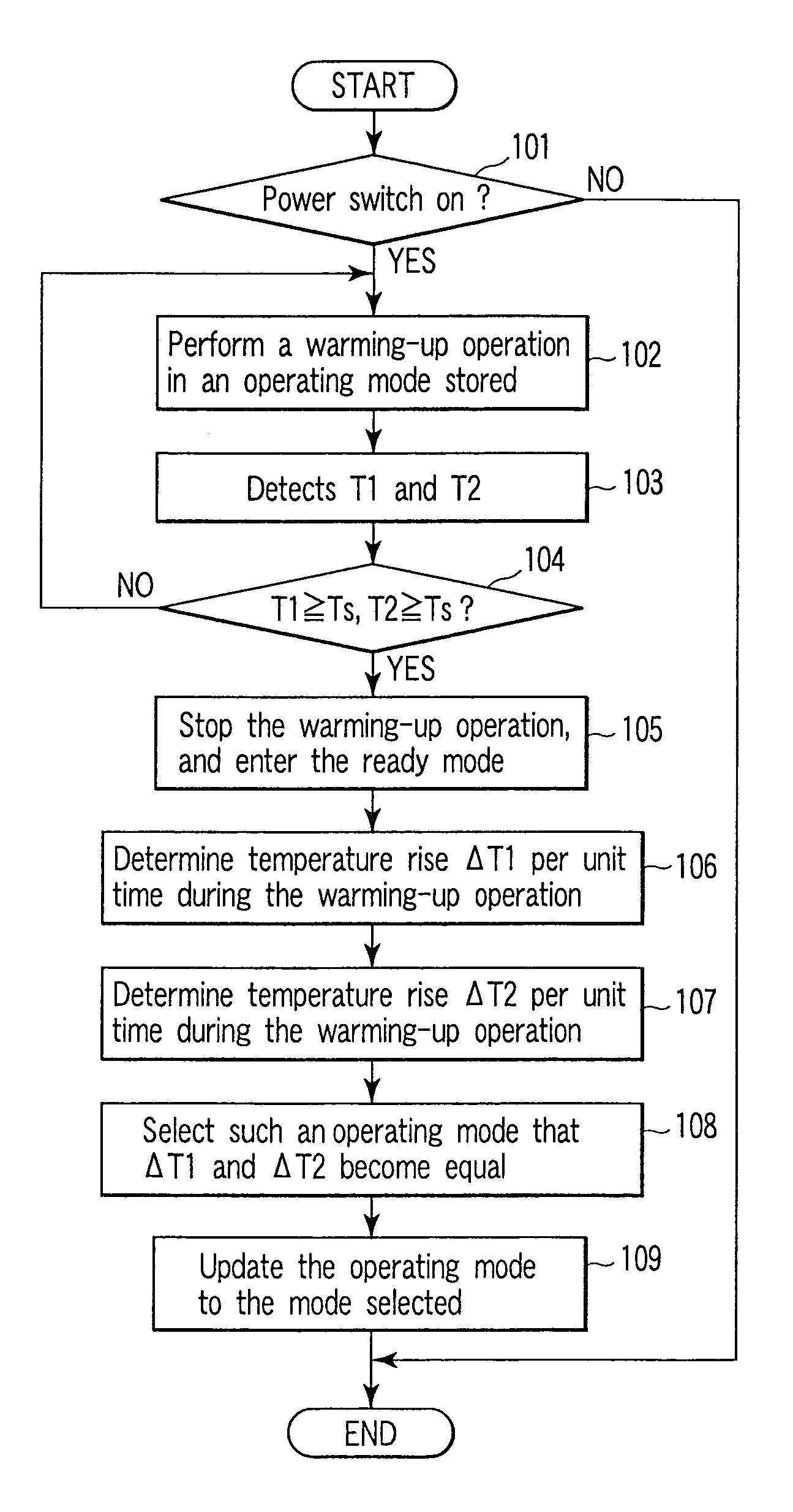
[0061]At the end of the warming-up operation, the temperature rise ΔT1 of the temperature T1 per unit time t during the warming-up operation is determined. The temperature rise ΔT2 of the temperature T2 per unit time t during the warming-up operation is determined, too. Then, an operating mode in which the coils are driven to make the temperature rises ΔT1 and ΔT2 equal is selected from those stored in the ROM 41. FIG. 10 shows the various operating modes that are stored in the ROM 41.
[0062]In the standard mode “11” the output of the center coil 21 is 1000 W, and the output of the side coils 22 and 23 is 1000 W, too (namely, the ratio is 1000:1000). If the temperature rise ΔT1 is greater than...
PUM
 Abstract
Description
Claims
Application Information