Extension structure for table saw

a table saw and extension structure technology, applied in the field of extension structure for table saws, can solve the problems of inconvenience to users, increased fabrication costs of conventional extension structures, and high cost of bearings, and achieve the effect of reducing disadvantages and/or obviating disadvantages

Inactive Publication Date: 2006-06-13
WANG WANG TIEN
View PDF9 Cites 15 Cited by
  • Summary
  • Abstract
  • Description
  • Claims
  • Application Information

AI Technical Summary

Benefits of technology

[0007]Another objective of the present invention is to provide an extension structure, wherein the extension table can be moved on the track rapidly, easily and conveniently by the sliding guide motion of the sliding interface unit so as to extend the working length of the table of the table saw.
[0008]A further objective of the present invention is to provide an extension structure, wherein the sliding interface unit consists of the columns, the slide plate and rollers having a price cheaper than that of the bearings, thereby greatly decreasing the costs of fabrication of the extension structure.
[0009]A further objective of the present invention is to provide an extension structure, wherein the extension structure is assembled easily and conveniently, thereby facilitating a user mounting the extension structure.

Problems solved by technology

However, the bearings are expensive, thereby greatly increasing the costs of fabrication of the conventional extension structure.
In addition, it is difficult to mount the multiple bearings between the extension table and the track, thereby causing inconvenience to a user when mounting the conventional extension structure.

Method used


Image

  • Extension structure for table saw
  • Extension structure for table saw
  • Extension structure for table saw

Examples


Embodiment Construction

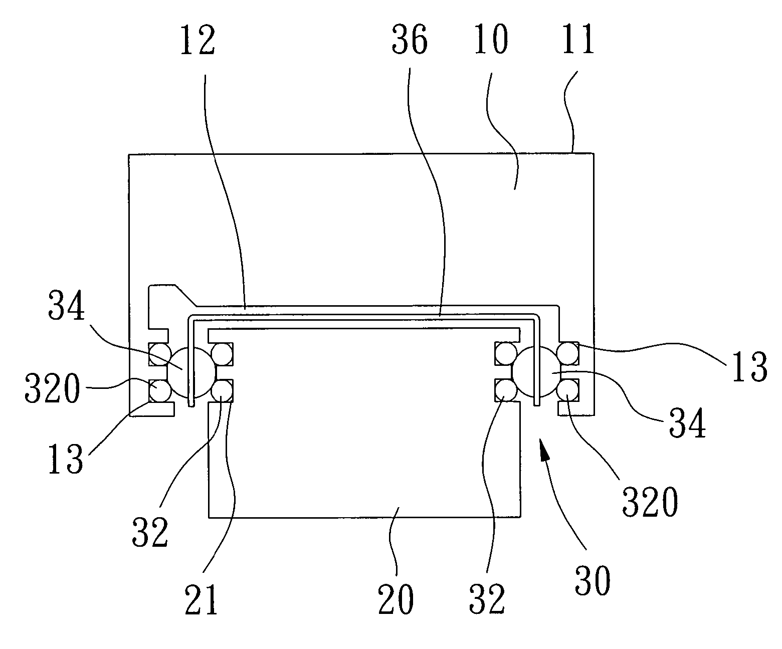
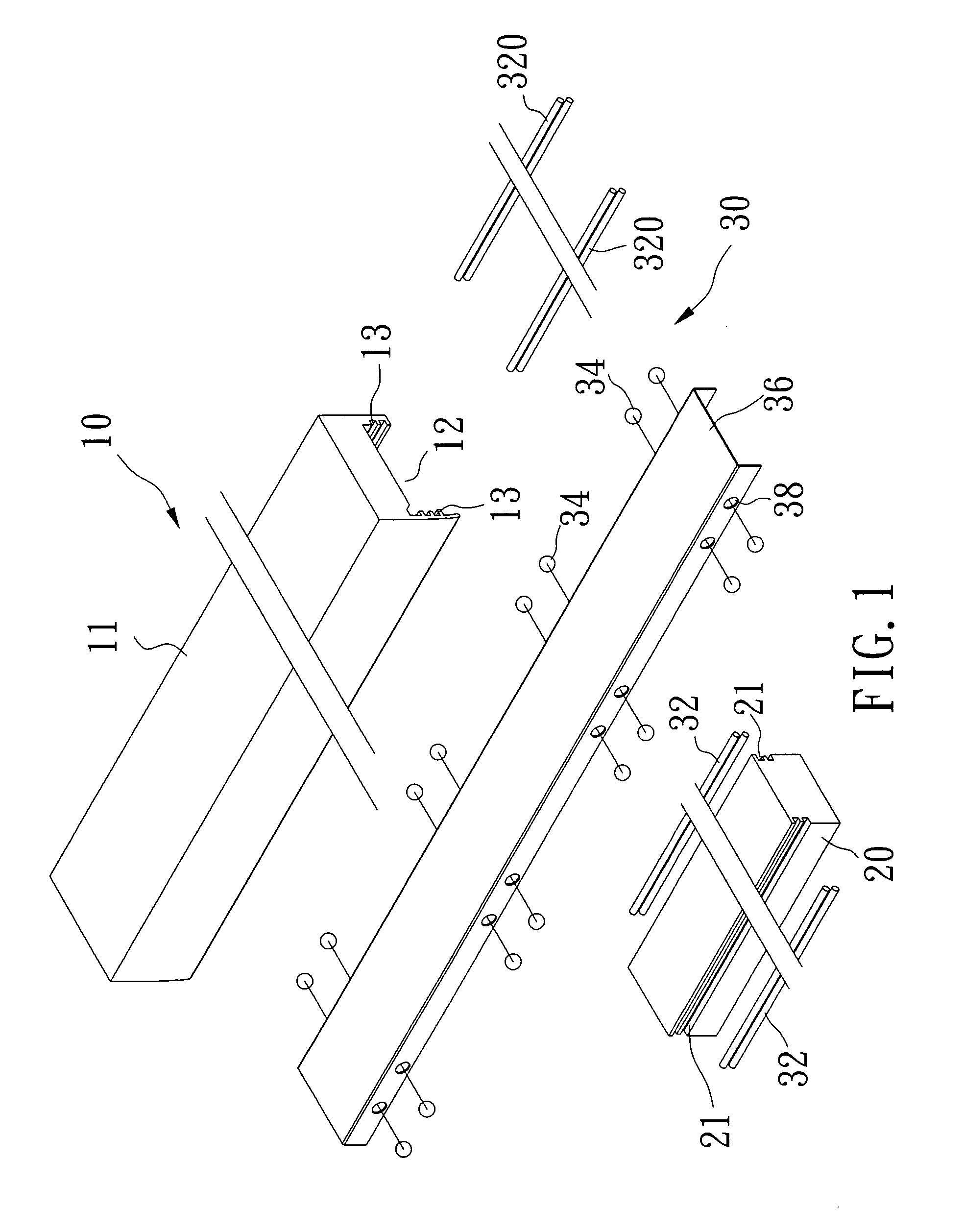
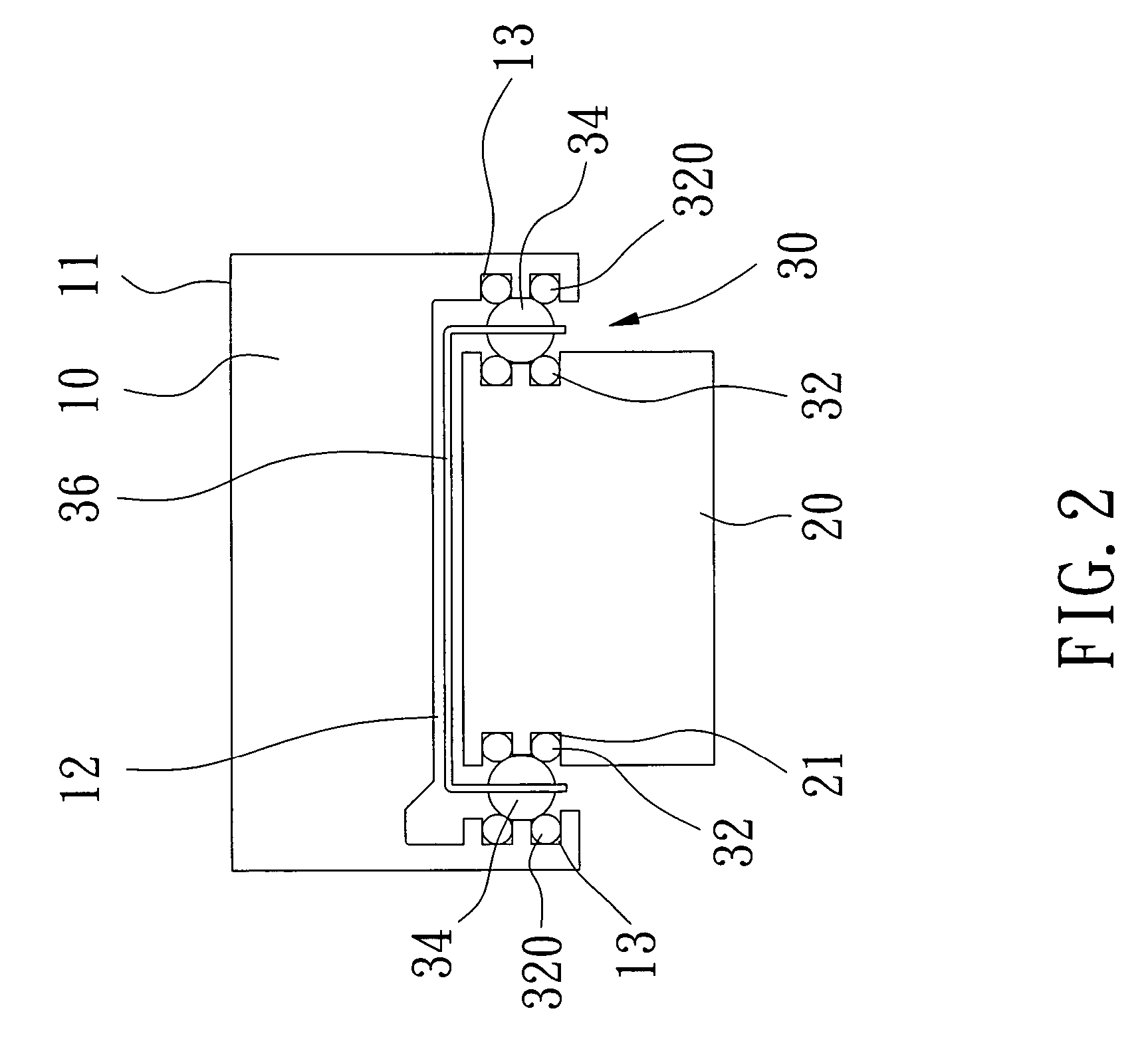
[0019]Referring to the drawings and initially to FIGS. 1–3, an extension structure for a table saw in accordance with the preferred embodiment of the present invention is mounted on a side of a table (not shown) of the table saw and comprises a track 20, an extension table 10, and a sliding interface unit 30.

[0020]The track 20 is secured on a saw base (not shown) of the table saw and has two opposite sides each formed with a first guide channel 21.

[0021]The extension table 10 is slidably mounted on the track 20. The extension table 10 has a substantially inverted U-shaped cross-section and has a top face formed with a working face 11 and a bottom face having two opposite sides each formed with a second guide channel 13 facing the respective first guide channel 21 of the track 20. The bottom face of the extension table 10 is formed with a receiving chamber 12 for receiving the track 20.

[0022]The sliding interface unit 30 is mounted between the extension table 10 and the track 20 and ...


PUM


Abstract

An extension structure includes a track, an extension table, and a sliding interface unit. Thus, the extension table can be moved on the track rapidly, easily and conveniently by the sliding guide motion of the sliding interface unit so as to extend the working length of the table of the table saw. In addition, the sliding interface unit has a cheaper price than that of the bearings, thereby decreasing the costs of fabrication of the extension structure. Further, the extension structure is assembled easily and conveniently, thereby facilitating a user mounting the extension structure.

Description

BACKGROUND OF THE INVENTION[0001]1. Field of the Invention[0002]The present invention relates to an extension structure for a table saw, and more particularly to an extension structure, wherein the extension table can be moved on the track rapidly, easily and conveniently by the sliding guide motion of the sliding interface unit so as to extend the working length of the table of the table saw.[0003]2. Description of the Related Art[0004]A conventional extension structure for a table saw is mounted on a side of a table of the table saw and comprises a track secured on a saw base of the table saw, an extension table slidably mounted on the track, and a plurality of bearings mounted between the extension table and the track. However, the bearings are expensive, thereby greatly increasing the costs of fabrication of the conventional extension structure. In addition, it is difficult to mount the multiple bearings between the extension table and the track, thereby causing inconvenience to...

Claims


Application Information

Patent Timeline
Patent Type & Authority Patents(United States)
IPC IPC(8): B25H1/00B27C9/00F16C29/00F16C29/04F16C33/61
CPCF16C29/00F16C33/61F16C29/04
Inventor WANG, WANG TIEN
Owner WANG WANG TIEN
Why Eureka
Try Eureka