Wellbore system with annular seal member

Inactive Publication Date: 2006-06-13
SWELLFIX UK
View PDF61 Cites 198 Cited by
  • Summary
  • Abstract
  • Description
  • Claims
  • Application Information

AI Technical Summary

Benefits of technology

[0009]To obtain an even better sealing system, it is preferred that the tubular element has been radially expanded in the borehole. In such application the seal member can be, for example, applied to the outer surface of the tubular element before radial expansion thereof so as to allow easy installation of the tubular element and the seal member in the borehole. Thereafter the tubular element can be radially expanded before or after swelling of the seal member due to contact with the selected fluid. However, to reduce the forces needed to expand the tubular element it is preferred that swelling of the seal member takes place after expansion of the tubular element.

Problems solved by technology

A limitation of the applicability of such packers is that the seal surfaces have to be well defined.
Although in general cement provides adequate sealing capability, there are some inherent drawbacks such as shrinking of the cement during hardening resulting in de-bonding of the cement sheath, or cracking of the cement layer after hardening, for example due to pressure and temperature shocks during operation of the well.

Method used


Image

  • Wellbore system with annular seal member
  • Wellbore system with annular seal member
  • Wellbore system with annular seal member

Examples


Embodiment Construction

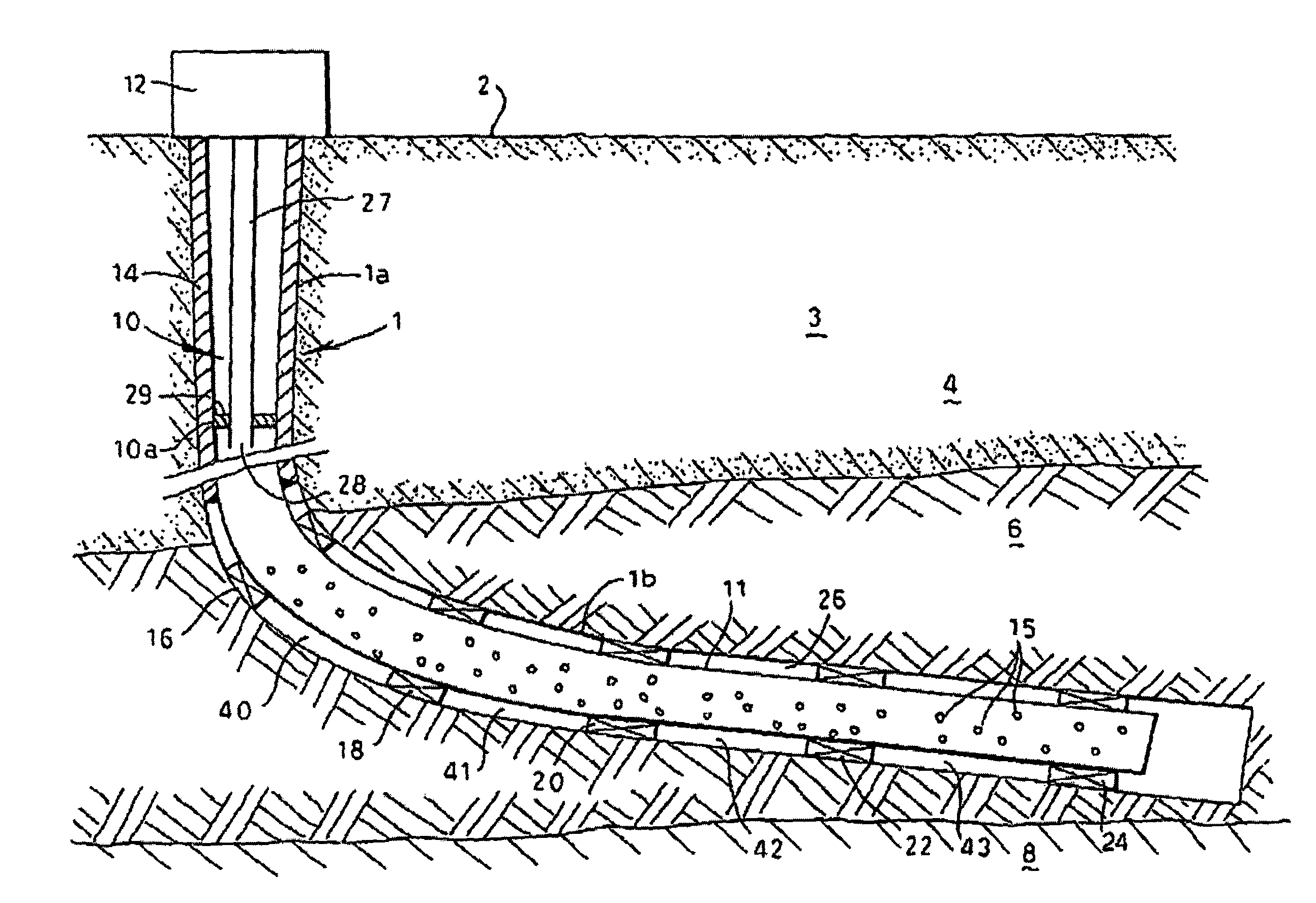
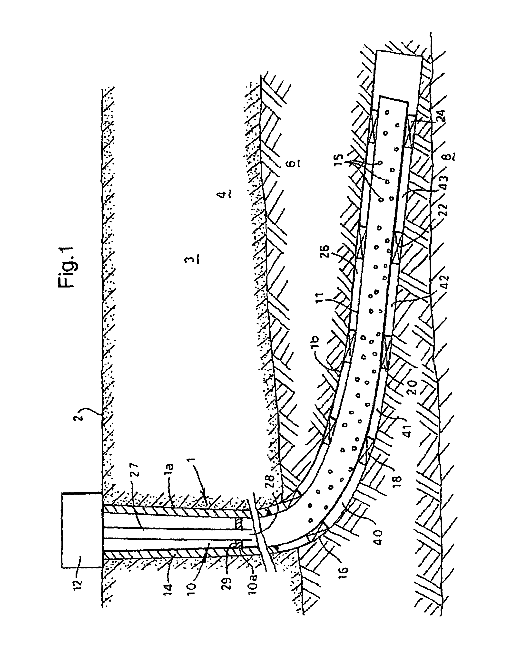
[0021]Referring to FIG. 1 there is shown a wellbore system including a borehole 1 which has been drilled from surface 2 into an earth formation 3. The borehole 1 penetrates an overburden layer 4 and a reservoir zone 6 containing hydrocarbon oil. A layer 8 containing formation water is commonly found below the reservoir zone. The borehole 1 has a substantially vertical upper section 1a extending through the overburden layer 4 and a substantially horizontal lower section 1b extending into the reservoir zone 6.

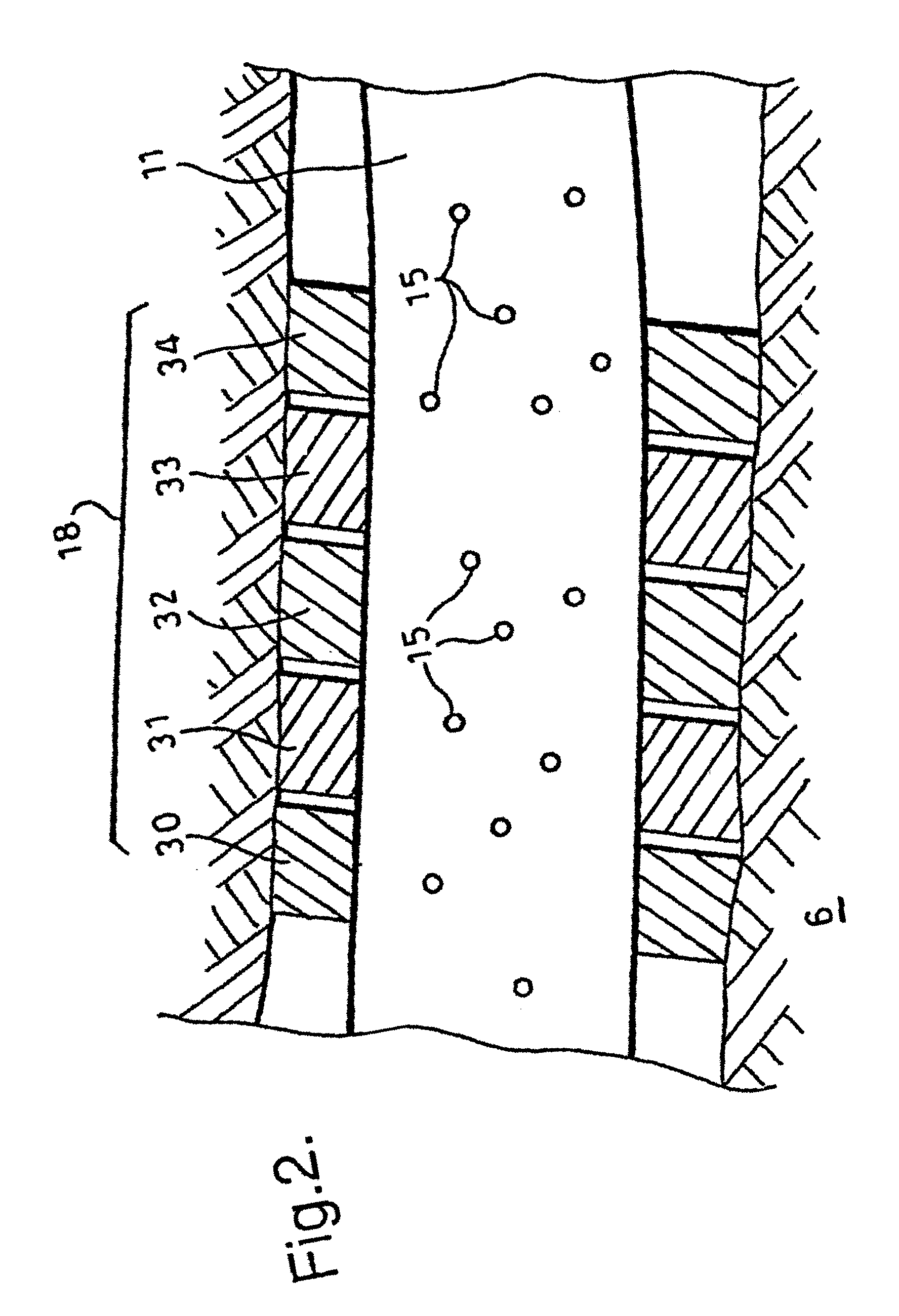
[0022]A tubular casing string 10 which is formed of a number of casing sections (not shown), extends from a wellhead 12 at surface into the upper borehole section 1a. A further tubular casing string 11 is provided with a plurality of perforations 15 (for sake of clarity not all perforations have been indicated by a reference numeral) which provide fluid communication between the interior of the casing string 11 and the exterior thereof. Annular seal assemblies 16, 18, 20, 22, 24 ...


PUM


Abstract

A wellbore system having a borehole extending into an earth formation, a tubular element extending into the borehole whereby a cylindrical wall surrounds the tubular element in a manner that an annular space is formed between the tubular element and the cylindrical wall, at least one seal member arranged in the annular space, each seal member being movable between a retracted mode in which the seal member has a first volume and an expanded mode in which the seal member has a second volume larger than the first volume, wherein the seal member in the expanded mode thereof seals the annular space, and wherein the seal member includes a material which swells upon contact with a selected fluid so as to move the seal member from the retracted mode to the expanded mode thereof.

Description

FIELD OF THE INVENTION[0001]The present invention relates to a wellbore system comprising a borehole extending into an earth formation, a tubular element extending into the borehole whereby a cylindrical wall surrounds the tubular element in a manner that an annular space is formed between the tubular element and the cylindrical wall, and wherein at least one seal member is arranged in said annular space. The cylindrical wall can be formed, for example, by the borehole wall or by another tubular element.BACKGROUND OF THE INVENTION[0002]Known seal members are, for example, packers which are arranged in the borehole to seal an annular space between a wellbore casing and a production tubing extending into the borehole. Such packer is radially deformable between a retracted position in which the packer is lowered into the borehole, and an expanded position in which the packer forms a seal. Activation of the packer can be by mechanical or hydraulic means. A limitation of the applicabilit...

Claims


Application Information

Patent Timeline
IPC IPC(8): E21B33/12E21B43/14E21B33/124E21B43/10
CPCE21B43/103E21B33/1208
Inventor BOSMA, MARTIN GERARD RENECORNELISSEN, ERIK KERST
Owner SWELLFIX UK
Why Eureka
Try Eureka