Freely rotatable binding for snowboarding and other single-board sports

a single-board sport, free-rotation technology, applied in the direction of skating, sports equipment, transportation and packaging, etc., can solve the problems of unnatural and awkward knee and ankle angle, limited use, and difficulty in walking to the ski lift with one foot removed from the snowboard, so as to reduce the probability of knee and ankle injury, increase the maneuverability of the snowboard, and increase the feeling of floating

Inactive Publication Date: 2006-06-13
COLE III CHARLES D
View PDF31 Cites 23 Cited by
  • Summary
  • Abstract
  • Description
  • Claims
  • Application Information

AI Technical Summary

Benefits of technology

[0008]The present invention relates to an improved sports board setup which allows for dynamic, free rotation of the bindings relative to the board. This design offers numerous advantages over currently available bindings for snowboards, for example, such as increased maneuverability of the snowboard, ease of use, and a significantly increased sensation of “floating” while riding. An additional, important advantage is the reduced probability of injury to knees and ankles resulting from use of the snowboard.

Problems solved by technology

This lack of movement of existing snowboard bindings results in limitations on their use.
For example, walking to a ski lift with one foot removed from the snowboard is very difficult, since the other foot is bound in a diagonal position across the snowboard.
This position results in an unnatural and awkward angle of the knee and ankle, and is a potential source of knee and ankle damage.
Additionally, if a person falls while riding the snowboard, the fixed bindings do not allow knees and ankles to remain aligned, which may also result in an increased likelihood of physical injury.
The static nature of the bindings also limits the maneuverability of the snowboard, when compared to the freedom experienced with skateboarding.
An example of the limitation on maneuverability is the inability to ride the snowboard backwards while facing forward.
No bearings are provided in the binding to allow free rotating movement, and some styles of adjustable bindings incorporate interfitting ribs which further impede free rotation even when the binding is unlocked.
Major repositioning of one or both feet is not possible while the board is moving.

Method used


Image

  • Freely rotatable binding for snowboarding and other single-board sports
  • Freely rotatable binding for snowboarding and other single-board sports
  • Freely rotatable binding for snowboarding and other single-board sports

Examples


Embodiment Construction

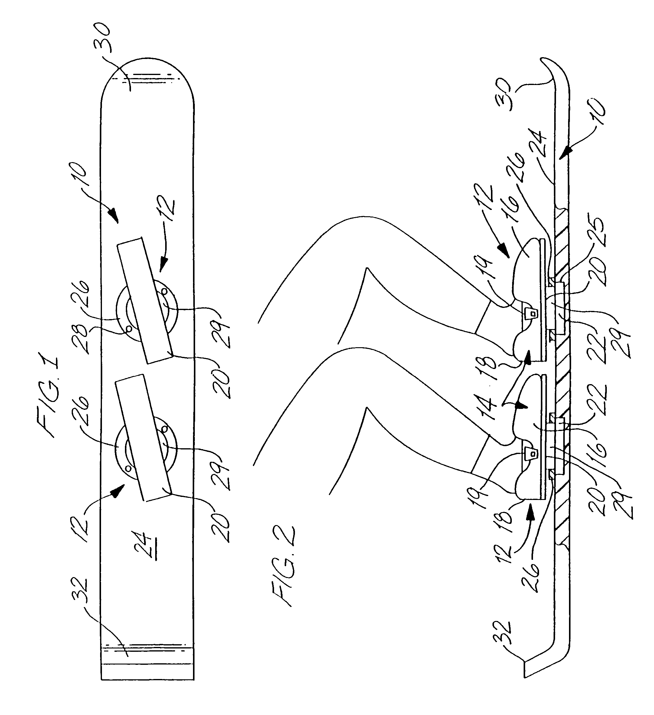
[0020]FIGS. 1 and 2 show a snowboard 10 with a pair of rotatable binding assemblies 12 spaced apart along a central longitudinal axis of the snowboard. Each rotatable binding assembly 12 incorporates a binding 14 having an instep element 16 and a heel element 18. When a booted foot is inserted into binding 14, the instep element is engaged by clamping it down onto the top of the boot, holding the boot firmly in place. The instep element prevents any forward or lateral motion of the foot relative to the binding. The heel element engages the heel of the boot and prevents any backward motion of the foot relative to the binding. A clamp 19, for securing the instep and heel elements to the boot may be of a buckle type, VELCRO, lacing, or other suitable type of clamp that will hold the instep and heel of the boot locked in place on the binding. Step-in or strap-in bindings are equally useful.

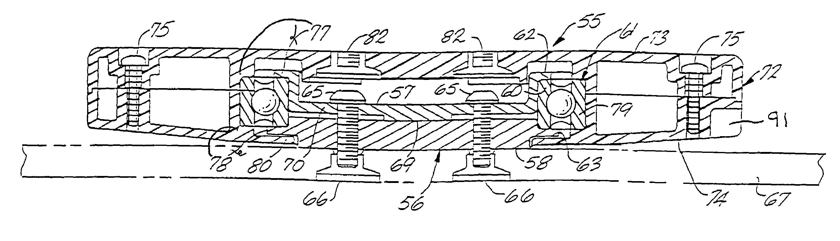
[0021]The heel and instep elements of binding 14 are attached to a rotatable plate 20. The binding...


PUM


Abstract

A freely rotatable binding base assembly for use on a board used in single-board sports such as snowboarding and slalom water skiing. A binding assembly mounted on and movably secured to the board, and is adapted to receive a conventional boot as worn by a rider. Additional features include a locking means for selectably blocking rotation, and a clutch for braking rotation by applying side loading to the board.

Description

CROSS-REFERENCE TO RELATED APPLICATIONS[0001]This application is a continuation application of U.S. patent application Ser. No. 10 / 325,520, filed Dec. 19, 2002, entitled “Freely Rotatable Binding For Snowboarding and Other Single-Board Sports”, which is a continuation application of U.S. patent application Ser. No. 09 / 622,632, filed Aug. 17, 2000, entitled “Freely Rotatable Binding For Snowboarding and Other Single-Board Sports”, which is a U.S. National Stage Application which claims benefit of International Application No. PCT / US99 / 03351, International Filing Date Feb. 17, 1999, entitled “Freely Rotatable Binding For Snowboarding and Other Single-Board Sports”, which claims benefit of U.S. Provisional Applications 60 / 074948, filed Feb. 17, 1998, entitled “Freely Rotatable Binding For Snowboarding and Other Single-Board-Sports”, and 60 / 090876, filed Jun. 26, 1998, entitled “Freely Rotatable Binding For Snowboarding and Other Single-Board Sports”; this application incorporates by re...

Claims


Application Information

Patent Timeline
Patent Type & Authority Patents(United States)
IPC IPC(8): A63C9/02A63C10/14A63C10/18A63C10/28
CPCA63C10/14A63C10/28A63C10/18A63C2203/54
Inventor COLE, III, CHARLES D.
Owner COLE III CHARLES D
Why Eureka
Try Eureka