Cutting machine push cart

a push cart and cutting machine technology, applied in the field of push carts, can solve the problems of comparatively heavy mobile support frame, safety concerns, and inconvenient operation

Inactive Publication Date: 2006-06-13
BLACK & DECKER INC
View PDF20 Cites 41 Cited by
  • Summary
  • Abstract
  • Description
  • Claims
  • Application Information

AI Technical Summary

Benefits of technology

[0006]The primary purpose of the present invention is to provide a cart to carry various types of cutting machine, that is adapted with telescoping rods for safe storage and control the limiting status of the legs when stretched up for use.
[0009]Another purpose yet of the present invention is to provide a cart to carry various types of cutting machine having the lower end of a cross leg of a support frame is pivoted to a pair of wheels for them to touch the ground when the cross leg on the other side is lifted to easily push the cart.

Problems solved by technology

However, the mobile support frame is comparatively heavy and it is not convenient since the user has to carry it from one jobsite to another.
Besides, it also presents safety concerns since the legs when retreated or extended are not provide with any safety means to secure them.
Furthermore, many brands and models of cutting machines generally available in the market have different specifications on the location of the positioning location, and the support frames for the cutting machines are not provided with an universal positioning structure for the cutting machines.
It is not cost efficiency due to the lacking in interchangeability among the support frames to force the user to abandon the existing support frame upon making a buy of another brand or model of the cutting machine.

Method used


Image

  • Cutting machine push cart
  • Cutting machine push cart
  • Cutting machine push cart

Examples


Embodiment Construction

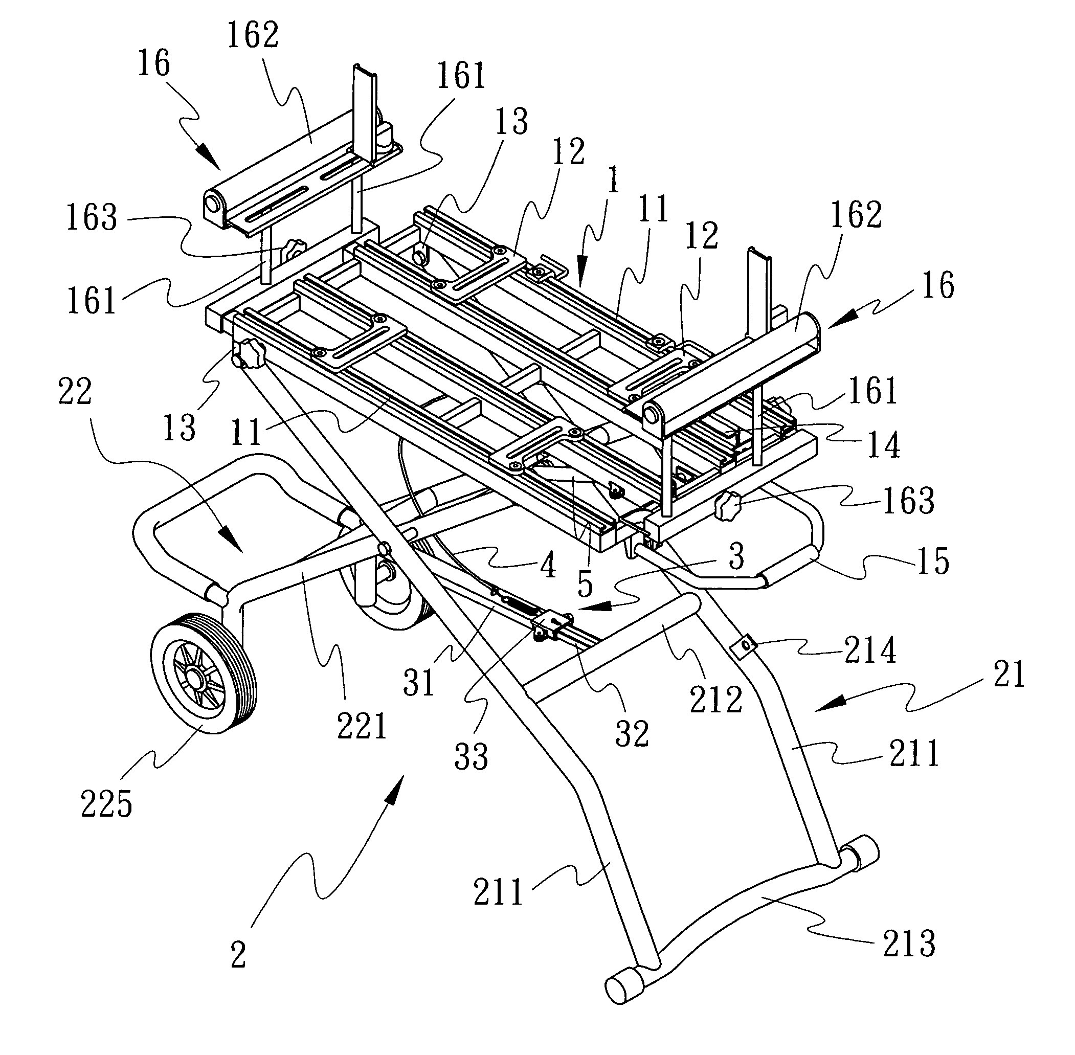
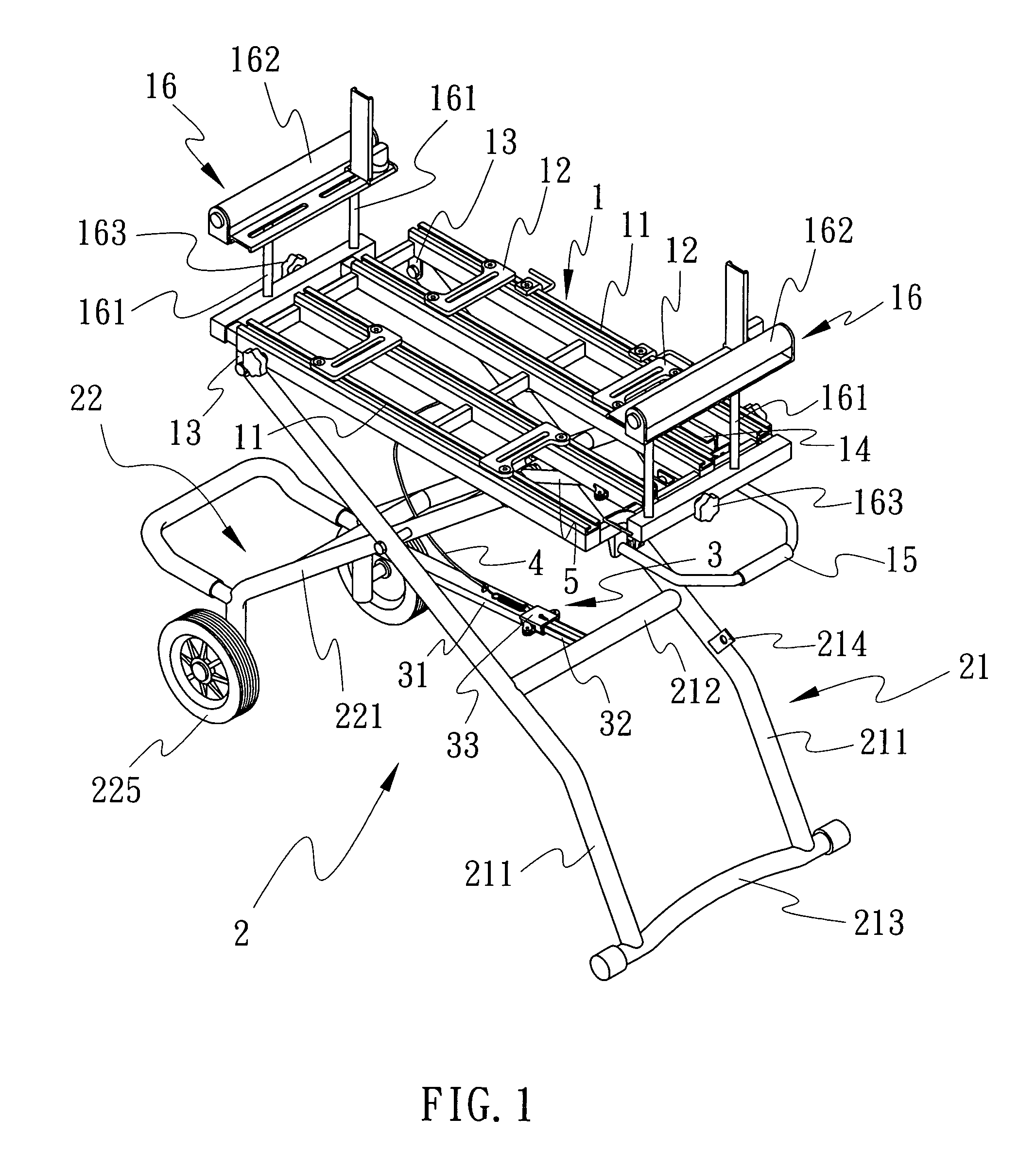
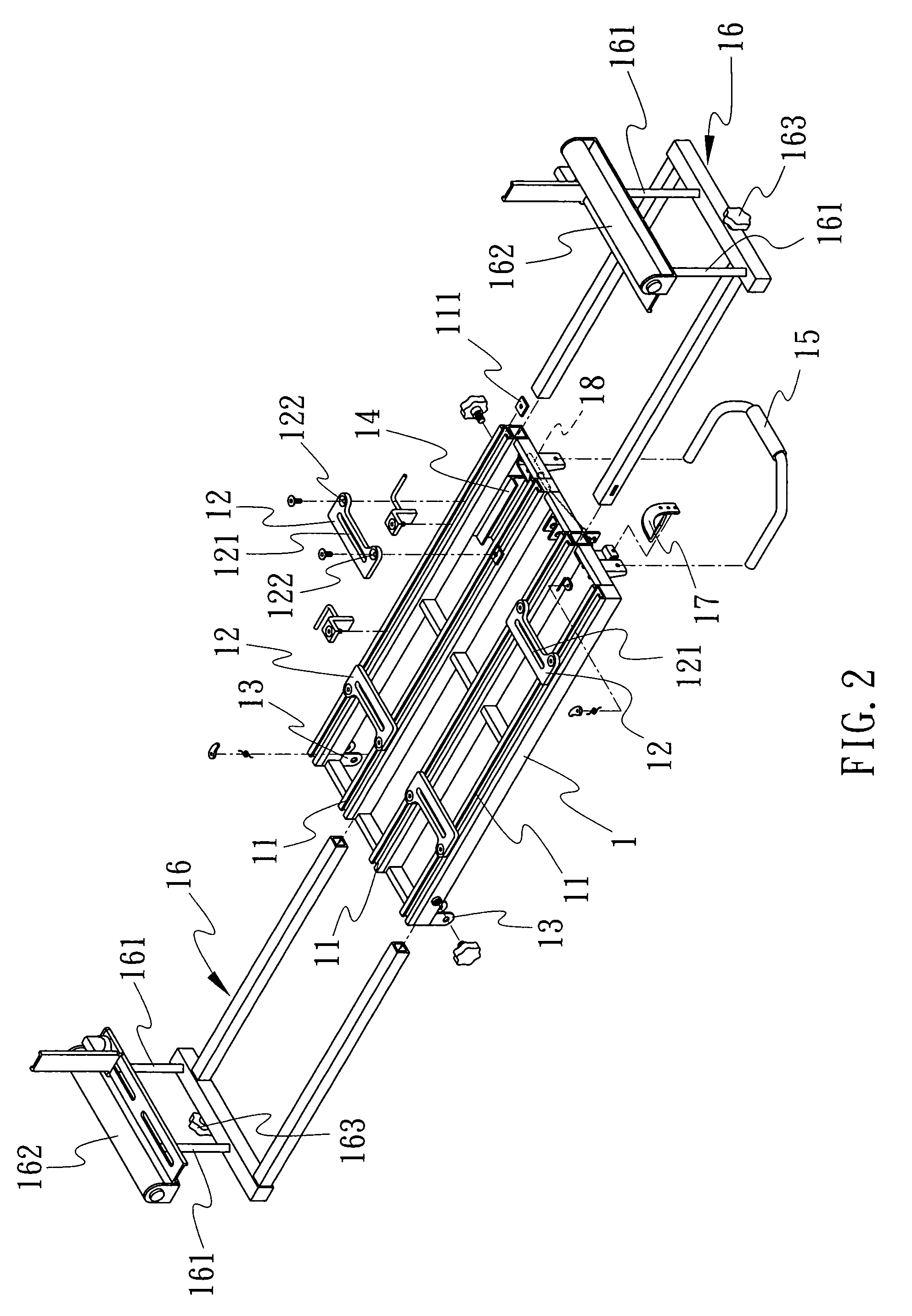
[0026]Referring to FIG. 1, a cutting machine push cart of the present invention is essentially comprised of a tabletop frame 1, a support frame 2 and a telescoping rod 3. Wherein, the tabletop frame I as illustrated in FIG. 2 is related to a rectangular frame. Multiple tracks 11 are provided at a given spacing and in parallel to one another between both shorter sided of the frame; multiple locking plates 111 each having a central locking hole is inserted into each track 11 for them to lock multiple positioning plates 12 onto the tracks 11. Two pivot holders 13, two chutes 14 and a handle 15 are provided to each side at the lower end of the tabletop frame 1. Two extension brackets 16 are respectively inserted into hollow tubes provided between both ends of the tabletop frame 1.

[0027]The support frame 2 as illustrated in FIG. 3 includes a first pair of cross legs 21 and a second pair of cross legs 22. The first pair of cross legs 21 is comprised of two side tubes 211, an upper brace 2...


PUM


Abstract

A foldable push cart to carry a cutting machine comprised of a tabletop frame, a support frame and a telescoping rod; adaptable to any cutting machine; an extension bracket on each side of the cart works with built-in oblique push block and slide rod depending on the length and height of the individual work piece; a hoisting cable controls work height and retraction of the cart; the telescoping rod provides self-locking safety function, and wheels are pivoted to a pair of cross legs.

Description

BACKGROUND OF THE INVENTION[0001](a) Field of the Invention[0002]The present invention is related to a push cart for carrying a cutting machine or similar machine, and more particularly, to one that is foldable, height adjustable, easy handling and adaptable to any model of a cutting machine.[0003](b) Description of the Prior Art[0004]Usually a cutting machine is fixed to a table for use. To make it mobile, a foldable support frame generally available in the market (as taught in U.S. Pat. Nos. 6,722,618 and 6,314,893) is essentially comprised of the support frame adapted with multiple telescoping legs. However, the mobile support frame is comparatively heavy and it is not convenient since the user has to carry it from one jobsite to another. Besides, it also presents safety concerns since the legs when retreated or extended are not provide with any safety means to secure them.[0005]Furthermore, many brands and models of cutting machines generally available in the market have differe...

Claims


Application Information

Patent Timeline
Patent Type & Authority Patents(United States)
IPC IPC(8): B62B1/00
CPCB25H1/04B62B1/26B25H1/10
Inventor WU, SAN-CHING
Owner BLACK & DECKER INC
Why Eureka
Try Eureka