Abutment structure used exclusively in tooth implantation

a technology of abutment structure and tooth implantation, which is applied in the field of abutment structure, can solve the problems of gum inflammation, easy control with precision, and cement spillage, and achieve the effect of reducing the cost of molding the artificial tooth

Inactive Publication Date: 2006-06-13
WU WEN YUEN
View PDF8 Cites 12 Cited by
  • Summary
  • Abstract
  • Description
  • Claims
  • Application Information

AI Technical Summary

Benefits of technology

[0006]The main objective of the present invention is to provide an abutment, which is provided in the center with an axial through hole enabling the excess amount of cement to be discharged from the upper segment of the abutment, thereby averting the deposit of the cement residue in the outer surface of the lower segment of the abutment and in the top of an implant. The cement residue can be thus easily removed to prevent the gums inflammation.
[0008]Another objective of the present invention is to provide an abutment structure comprising a crown and a fixation pin, by which the abutments of various inclinations can be used in the implantation of an implant into an incisor socketed bone without the angular deviation. The abutment can be joined together with the crown by the fixation pin in various manners, thereby reducing the cost of molding the artificial tooth as well as the abutment inventory.

Problems solved by technology

In view of the fact that the application of the cement “G” can not be easily controlled with precision in terms of quantity of the cement “G”, it is therefore likely that an excessive amount of the cement is injected into the cavity 21 of the implant 20, thereby resulting in the spilling of the cement “G”.
Such a mishap often results in a gums inflammation, or a situation in which the implant 20 is apt to become loosened by a chewing action.
The abutment 10 described above is used in an upright manner in the molar implantation; nevertheless it is not suitable for use in the incisor implantation.
Such angular deviations as described above often result in failure of implantation.
In addition, there is lack of a standardized implantation method by which the implant 20 is always implanted into the socketed bone “I” at a correct angle.

Method used


Image

  • Abutment structure used exclusively in tooth implantation
  • Abutment structure used exclusively in tooth implantation
  • Abutment structure used exclusively in tooth implantation

Examples


Embodiment Construction

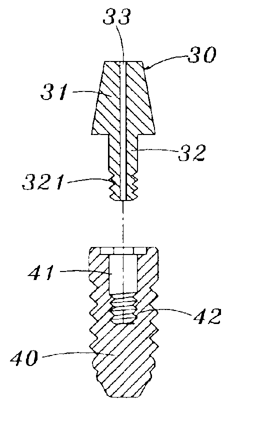
[0031]Referring to FIG. 5 of the drawing an abutment structure according to a first preferred embodiment of the present invention is illustrated. The abutment 30 has an upper segment 31 which is of conical construction and is provided with a flat top. The abutment 30 has a lower segment 32 which is or a columnar construction and is smaller in diameter than the upper segment 31. The lower segment 32 is provided at a bottom end with male threads 321. The lower segment 32 is further provided in the center with an axial through hole 33 extending through the bottom end of the lower segment 32 toward the top of the upper segment 31. As illustrated, the axial through hole has a uniform diameter along its length.

[0032]As shown in FIG. 6, the implantation according to a preferring embodiment of the present invention is similar in operation to the current tooth implantation. An implant 40 is first inserted into a socketed bone I. The implant 40 is provided With a threaded hole 41 into which a...


PUM

PropertyMeasurementUnit
abutment structureaaaaaaaaaa
diameteraaaaaaaaaa
angleaaaaaaaaaa

Abstract

A dental abutment is provided with an axial through hole and is fastened at a lower segment thereof with an implant in conjunction with a cement which is infected into a threaded hole of the implant. An excess amount of the cement is forced out via the axial through hole of the abutment such that the cement is deposited on a flat top of the abutment to facilitate the removing of the cement residue and to minimize the likelihood of a gums inflammation which may be resulted from an incomplete removal of the cement residue.

Description

FIELD OF THE PRESENT INVENTION[0001]The present invention relates generally to a tooth implantation, and more particularly to an abutment structure which is designed to enhance efficiency of the tooth implantation, and to minimize the likelihood of the post-operational gums inflammation which is resulted from an incomplete removal of cement.BACKGROUND OF THE PRESENT INVENTION[0002]Referring to FIG. 1 of the drawing, a prior art dental abutment 10 has an upper segment 11, and a lower segment 12 which is provided at the free end with male threads 121. The upper segment 11 is dimensioned to fit into a tooth “T”, while the lower segment 12 is fastened with an implant 20 such that the male threads 121 of the lower segment 12 are engaged with female threads 22 of a cavity 21 of the implant 20. The engagement is reinforced by a cement “G” which is injected into the cavity 21.[0003]As shown in FIG. 2, a socketed bone “I” is provided with a socket into which the implant 20 is fitted. In othe...

Claims


Application Information

Patent Timeline
Patent Type & Authority Patents(United States)
IPC IPC(8): A61C8/00
CPCA61C8/0069A61C8/005A61C8/00A61C8/0048A61C8/006
Inventor WU, WEN-YUEN
Owner WU WEN YUEN
Why Eureka
Try Eureka