Locking nail and aim-taking apparatus

a technology of locking nail and target, which is applied in the field of bone nail and target device, can solve the problem of not being able to precisely identify the position of the cross-bores only in mechanical ways by using known means, and achieve the effect of easy determination of the position of the distal cross-bores

Inactive Publication Date: 2006-06-13
STRYKER EURO OPERATIONS HLDG LLC
View PDF9 Cites 8 Cited by
  • Summary
  • Abstract
  • Description
  • Claims
  • Application Information

AI Technical Summary

Benefits of technology

[0005]It is the object of the invention to provide a locking nail which makes it possible to

Problems solved by technology

A problem in employing such locking nails is how to identify the position of the cross-bores to drill a hole in the corticalis in the right place from outside.
Although the position of the cross-bores may be determined by means of X-rays in a relatively precise way

Method used


Image

  • Locking nail and aim-taking apparatus
  • Locking nail and aim-taking apparatus
  • Locking nail and aim-taking apparatus

Examples


Embodiment Construction

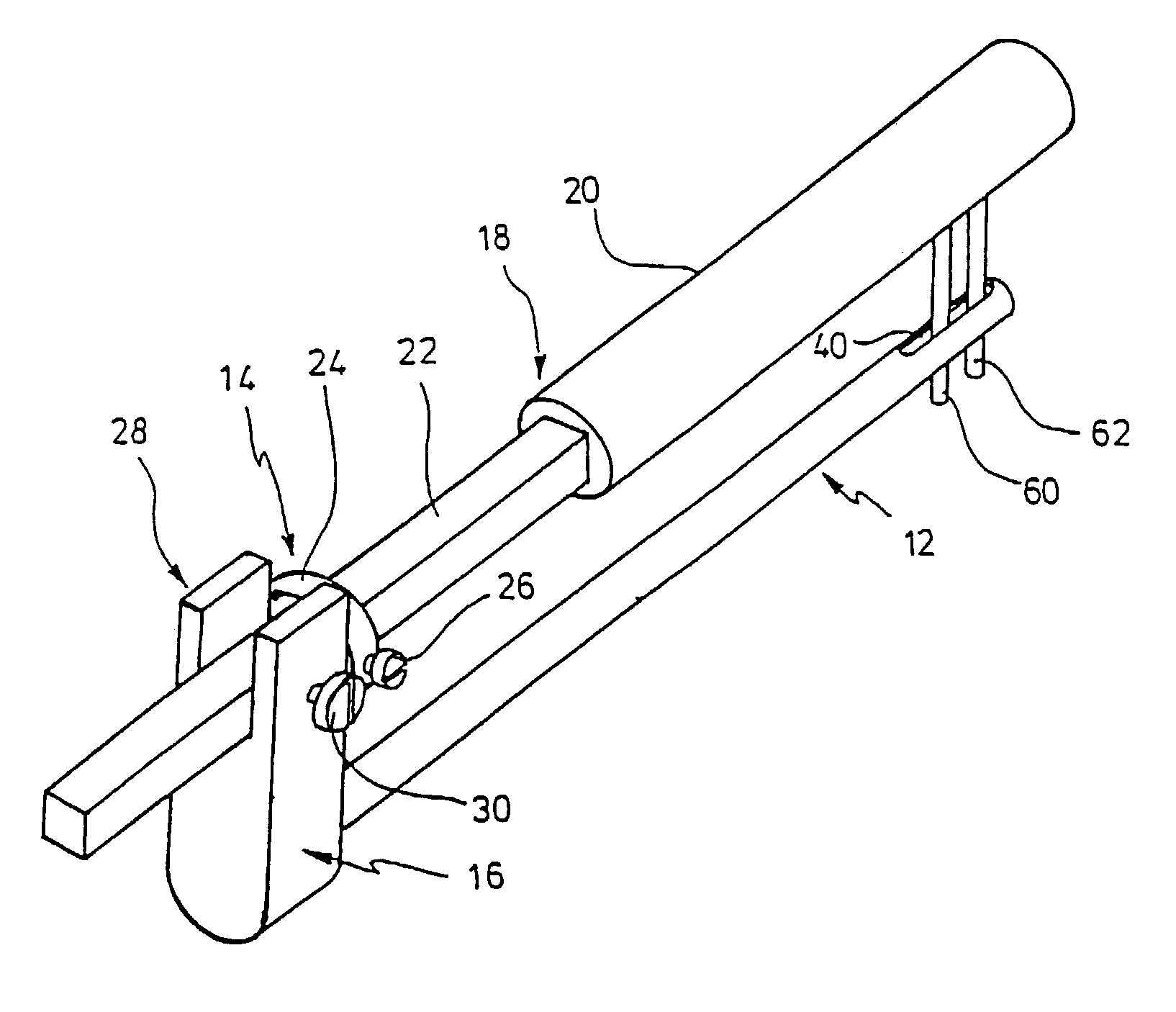
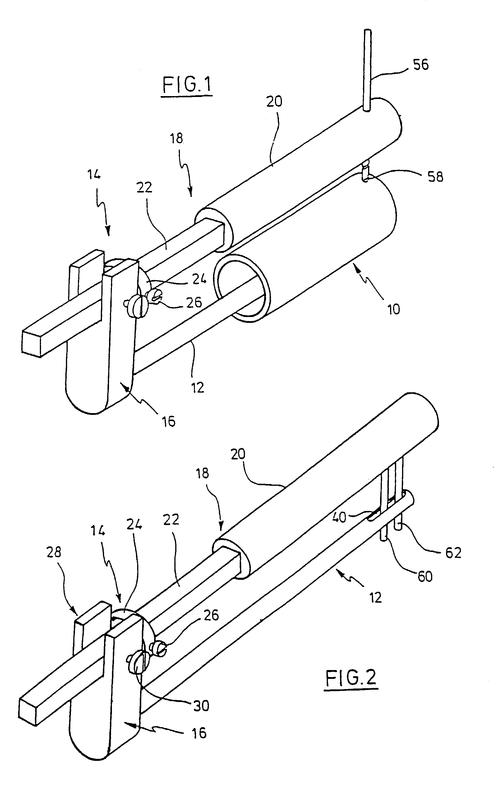
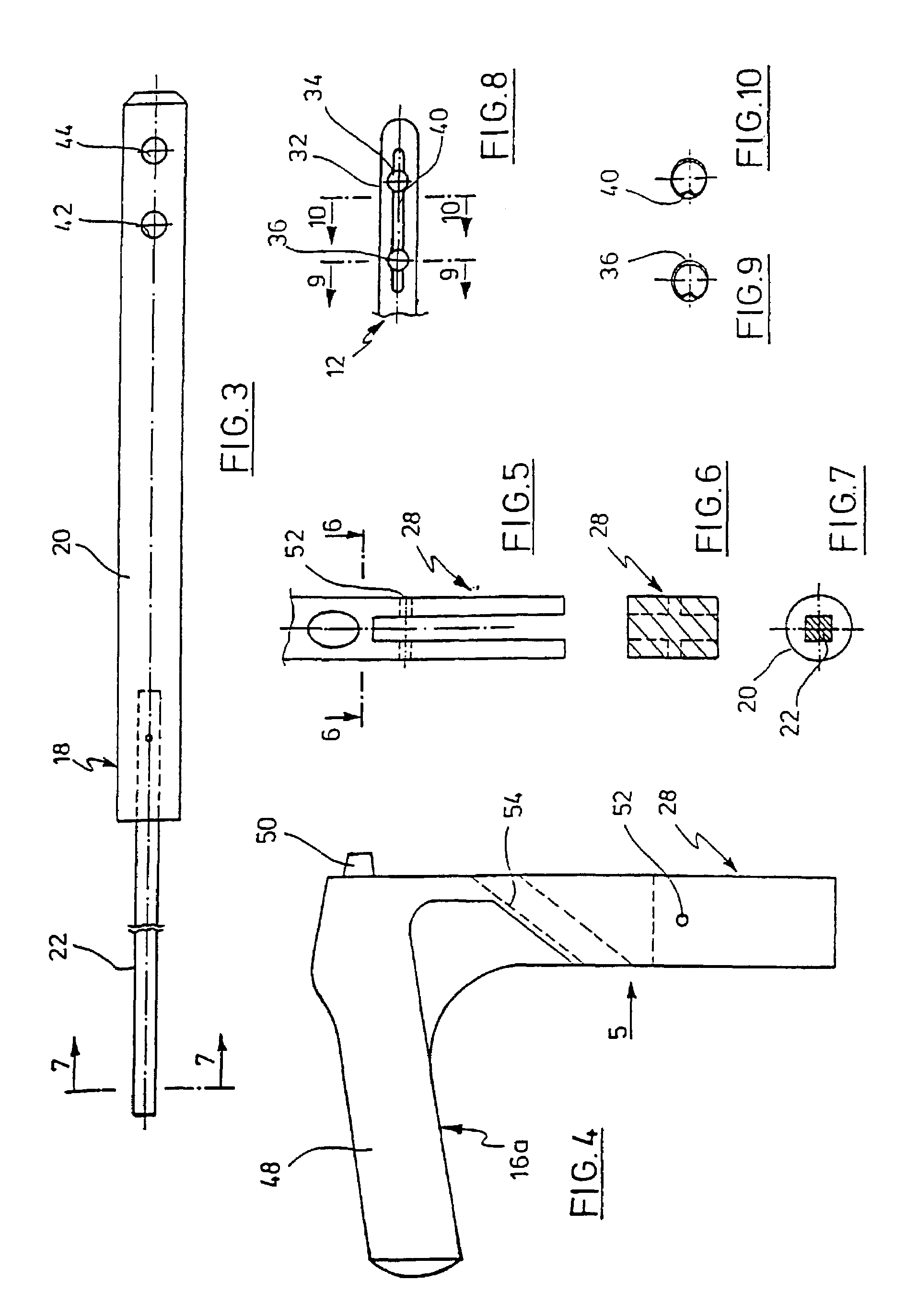
[0023]Referring to FIG. 1, a cylindrical hollow bone 10 is outlined which requires to be cared for by means of a locking nail 12 which is only outlined as well. A targeting apparatus 14, which is outlined in FIG. 1, has a handle portion 16 to which the proximal end of nail 12 is connected in an axially and rotationally stable way. The type of connection is not shown. It is known per se. A targeting bar 18, which consists of a distal portion 20 and a proximal portion 22, extends in parallel with nail 12. Proximal portion 22 is a metallic square. Distal portion 20 is cylindrical and is formed from an elastic plastic material such as PTFE. Portions 20, 22 are interconnected in an appropriate way which, however, is not shown. Seated in a rotationally stable way on portion 22 of targeting bar 18 is a fixing ring 24 which, however, is axially displaceable with the axial position being locatable by means of a fixing screw 26. Handle portion 16 has a bifurcated portion 28 where the gap betw...


PUM


Abstract

A locking nail for treating fractures of tubular bones has two parallel cross-bores that are axially spaced apart provided on the distal end of said nail and optionally at least one additional cross-bore is provided on the proximal end thereof for receiving bone screws. The nail includes a groove which is parallel to a longitudinal axis of the nail is formed into the outer side of the nail. The groove extends into the distal bores on both sides and merges into the bore. The longitudinal axis of the groove intersects the axis of each cross-bore.

Description

BACKGROUND OF THE INVENTION[0001]This invention relates to a bone nail and a targeting device for locating cross-locking holes in the bone nail.[0002]Locking nails to care for fractures in cylindrical hollow bones are widely used. Their utilization is described, for example, in “The Journal of Trauma” of 1993, Vol. 35, No. 5, pp. 772 to 775. It is the typical of such locking nails that two cross-bores are disposed at the distal end and at least one cross-bore is disposed at the proximal end. Bone screws are passed through the cross-bores. They are screwed into the corticalis at opposed sides. This secures the locking nail axially and against a rotation.[0003]A problem in employing such locking nails is how to identify the position of the cross-bores to drill a hole in the corticalis in the right place from outside. A number of aim-taking apparatus has become known, which work with X-rays to identify the position of the cross-bores relative to an aiming or targeting apparatus. Theref...

Claims


Application Information

Patent Timeline
IPC IPC(8): A61B17/72A61B17/17A61B17/58
CPCA61B17/72A61B17/1725
Inventor ANASTOPOULOS, GEORGEROBIONECK, PAUL BERND
Owner STRYKER EURO OPERATIONS HLDG LLC
Why Eureka
Try Eureka