Signal processing apparatus which suppresses a color signal according to luminance level

a signal processing and luminance level technology, applied in the field ofpicked-up image signal processing apparatus, can solve the problems of color signal degradation, inability to color-suppress a correctly saturated pixel, etc., and achieve the effect of preventing image degradation

Inactive Publication Date: 2006-06-13
CANON KK
View PDF18 Cites 24 Cited by
  • Summary
  • Abstract
  • Description
  • Claims
  • Application Information

AI Technical Summary

Benefits of technology

[0014]The present invention has been made in view of the above-described problems, and an object of the present invention is to provide a signal processing apparatus and a picked-up image signal processing method both of which restrain a color signal from being influenced by processing performed by a color processing system, thereby enabling signal processing which prevents degradation of image quality.

Problems solved by technology

If the above-described color suppression is performed, the surroundings of the subject are color-suppressed, so that the color information of the final output image may be lost to cause degradation of its image quality.
Furthermore, the frequency band of a signal for detection of a saturated high luminance portion of the CCD 1 differs from those of color-difference signals to be color-suppressed, and if the frequency band of a signal for detection of a high luminance portion is narrower than those of color-difference signals to be color-suppressed, it may be impossible to color-suppress a correctly saturated pixel.

Method used


Image

  • Signal processing apparatus which suppresses a color signal according to luminance level
  • Signal processing apparatus which suppresses a color signal according to luminance level
  • Signal processing apparatus which suppresses a color signal according to luminance level

Examples


first embodiment

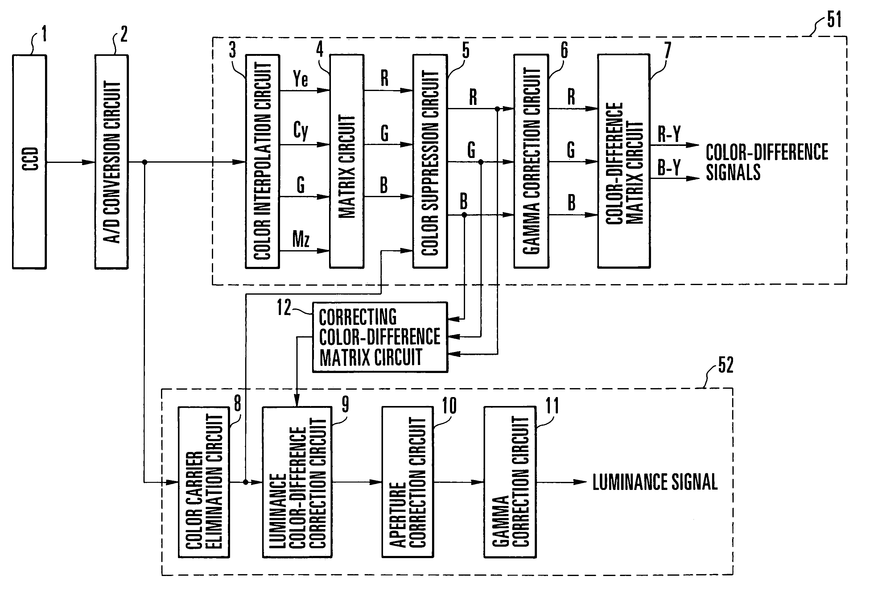
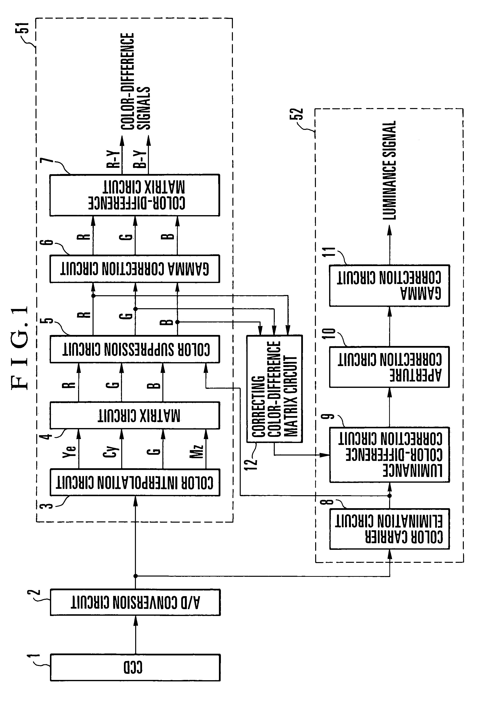
[0039]FIG. 1 is a schematic block diagram showing a signal processing apparatus according to the present invention. Each block shown in FIG. 1 will be described below.

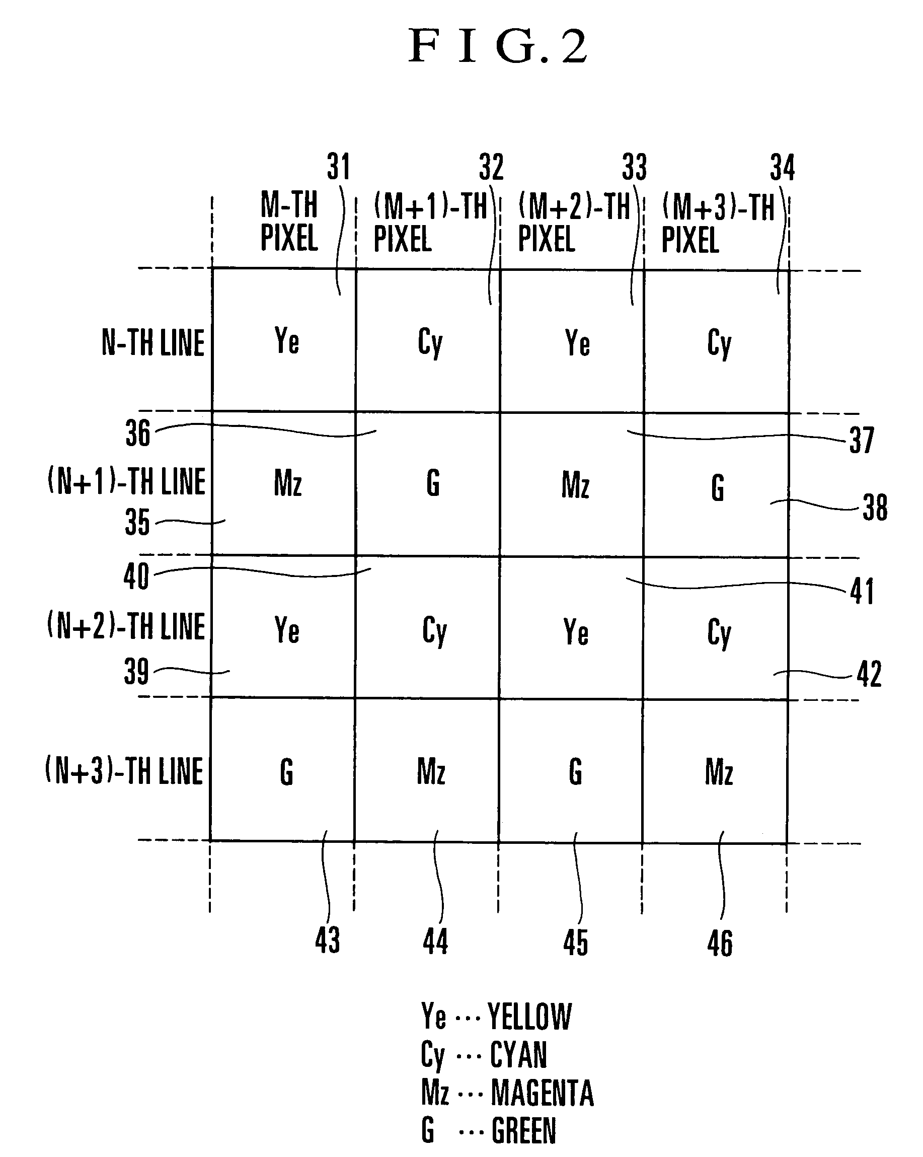
[0040]A CCD 1 serves as image pickup means, and converts a received light image into an electrical signal and stores the electrical signal as an analog signal, and outputs the analog signal. Color filters are disposed on the surface of the light receiving part of the CCD 1. In general, color filters are divided into two major types, complementary-color type color filters and pure-color type color filters. The complementary-color type color filters include, for example, a yellow (Ye) filter, a cyan (Cy) filter, a magenta (Mz) filter and a green (G) filter, while the pure-color type color filters include, for example, a red (R) filter, a green (G) filter and a blue (B) filter. In the first embodiment as well as any other embodiment to be described later, the combination and arrangement of these two types of filters may b...

second embodiment

[0081]FIG. 6 is a schematic block diagram showing a signal processing apparatus according to the present invention.

[0082]In the signal processing apparatus according to the second embodiment of the present invention, the CCD 1, the A / D conversion circuit 2, the color interpolation circuit 3, the matrix circuit 4, the gamma correction circuit 6, the color-difference matrix circuit 7, the color carrier elimination circuit 8, the luminance color-difference correction circuit 9, the aperture correction circuit 10, the gamma correction circuit 11 and the correcting color-difference matrix circuit 12 are identical to the corresponding processing blocks of the signal processing apparatus according to the first embodiment of the present invention. However, a color suppression circuit 13 differs from the color suppression circuit 5 used in the first embodiment of the present invention, and is characterized by being capable of detecting a low luminance portion or a high luminance portion of a...

third embodiment

[0101]FIGS. 8 and 8A are schematic block diagrams showing a signal processing apparatus according to the present invention.

[0102]In the signal processing apparatus according to the third embodiment of the present invention, the CCD 1, the A / D conversion circuit 2, the color interpolation circuit 3, the matrix circuit 4, the gamma correction circuit 6, the color-difference matrix circuit 7, the color carrier elimination circuit 8, the luminance color-difference correction circuit 9, the aperture correction circuit 10, the gamma correction circuit 11 and the correcting color-difference matrix circuit 12 are identical to the corresponding processing blocks of the signal processing apparatus according to the first embodiment of the present invention. However, a color suppression circuit 21 differs from the color suppression circuit 5 used in the first embodiment of the present invention, and is characterized by being capable of detecting a low luminance portion or a high luminance porti...


PUM


Abstract

To provide a signal processing apparatus and an image pickup signal processing method both of which restrain a color signal from being influenced by band limitation in a color processing system, thereby enabling signal processing which produces an undegraded image, the processing of color-suppressing RGB signals or complementary color signals is performed between a color interpolation circuit and a color-difference matrix circuit. Otherwise, the processing of suppressing a color signal is performed in front of the color interpolation circuit.

Description

BACKGROUND OF THE INVENTION[0001]1. Field of the Invention[0002]The present invention relates to a picked-up image signal processing apparatus and a picked-up image signal processing method both of which convert a subject image into an image signal and process the image signal as a luminance signal and color-difference signals.[0003]2. Description of Related Art[0004]Conventionally, in a picked-up image signal processing apparatus which is arranged to convert a subject image into an image signal and process the image signal as a luminance signal and color-difference signals, the image signal is processed by signal processing blocks such as those shown in FIG. 13.[0005]A received light image of a subject is converted into an electrical signal by a CCD 1. The electrical signal is converted from its analog form to a digital form by an A / D conversion circuit 2. The obtained digital signal is processed in both a color processing system 51 and a luminance processing system 52.[0006]In the...

Claims


Application Information

Patent Timeline
Patent Type & Authority Patents(United States)
IPC IPC(8): H04N5/228H04N5/335H04N9/04H04N9/083H04N5/202H04N9/00H04N9/07H04N9/64H04N9/68H04N9/77
CPCH04N9/77H04N9/07H04N23/12
Inventor HONMA, YOSHIHIRO
Owner CANON KK
Why Eureka
Try Eureka