Method for magnetic field reduction using the decoupling effects of multiple coil systems

a technology of decoupling effect and magnetic field reduction, which is applied in the direction of unwanted magnetic/electric effect reduction/prevention, inductance without magnetic core, fixed inductance, etc., can solve the problems of unsuitable large-scale power reactor construction, and inability to meet the needs of large-scale power reactors. , to achieve the effect of external magnetic field reduction

Inactive Publication Date: 2006-06-13
TRENCH
View PDF18 Cites 2 Cited by
  • Summary
  • Abstract
  • Description
  • Claims
  • Application Information

AI Technical Summary

Benefits of technology

[0014]It is a further object of the present invention to provide a method to achieve external magnetic field reduction.

Problems solved by technology

In other words, access to humans was limited by fencing or the use of tall mounting structures.
However, this construction is not suitable for large power reactors due to the problem of cooling and the extremely high cost associated with it.
This methodology is not practical for large power reactors because of the high cost associated with it.
These methodologies are not practical for large power reactors because of the very high cost associated to it.
In most cases, they were not suitable as outdoor units where the laminated steel yokes must be protected against the weather.
This type of shielding is not applicable to air core power reactors, which are very much larger physically, of very much higher voltage ratings and, almost always, installed out of doors.
The huge amount of laminated steel required and the need to protect it from the weather would make the cost prohibitive.

Method used


Image

  • Method for magnetic field reduction using the decoupling effects of multiple coil systems
  • Method for magnetic field reduction using the decoupling effects of multiple coil systems
  • Method for magnetic field reduction using the decoupling effects of multiple coil systems

Examples


Embodiment Construction

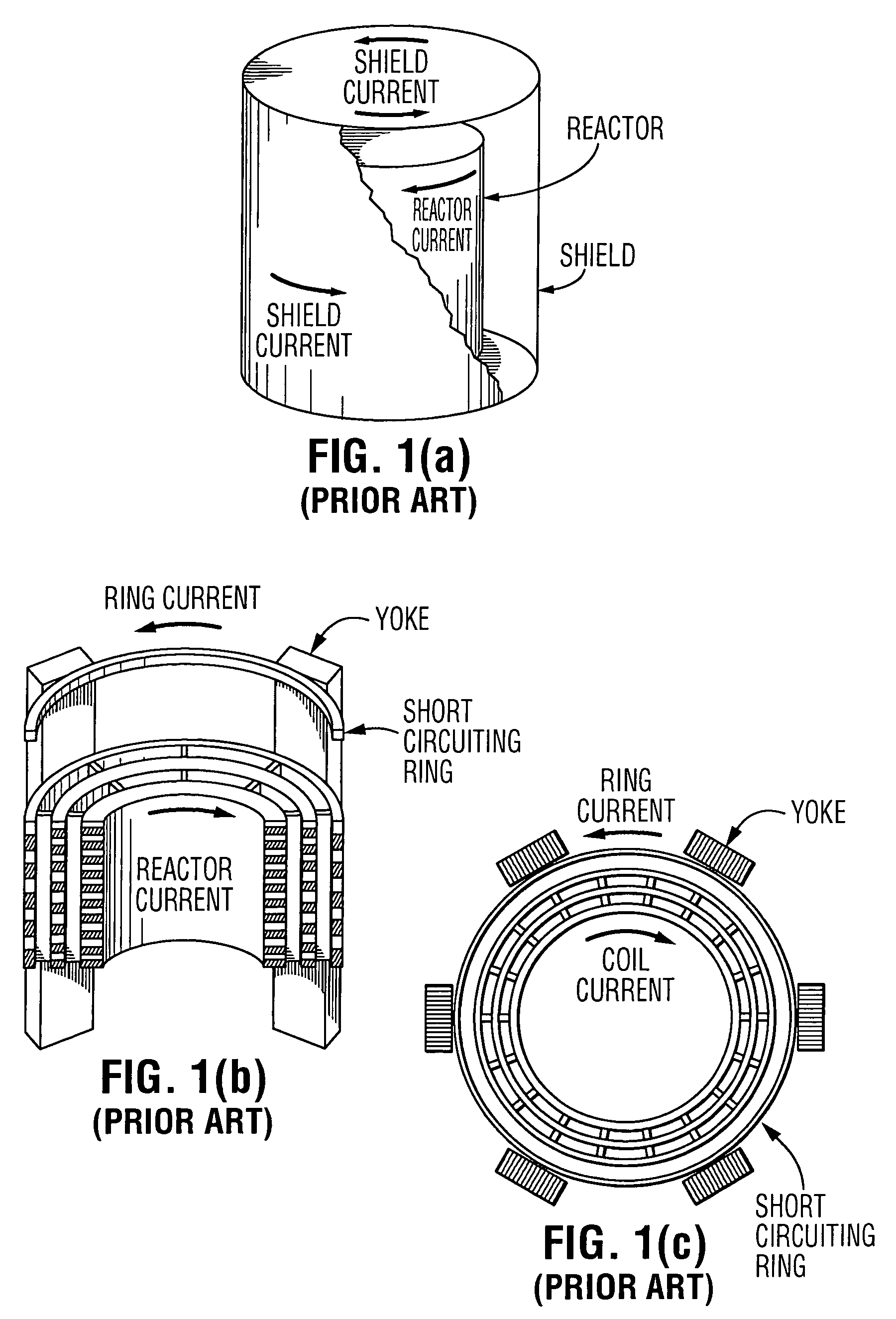
[0027]It is well known that standard installations of air core reactors generally employ a single coil per electrical phase. In some instances, where the electrical power rating is very large, multiple coils per phase may be employed whereby the coils would usually be configured to achieve the maximum positive coupling in order to reduce costs.

[0028]It follows that using multiple coil systems per phase in order to achieve magnetic field reduction over a large physical area has not been a technique previously used. In fact, the use of multiple coils per phase is usually not desirable since a single coil per phase system is always lower cost.

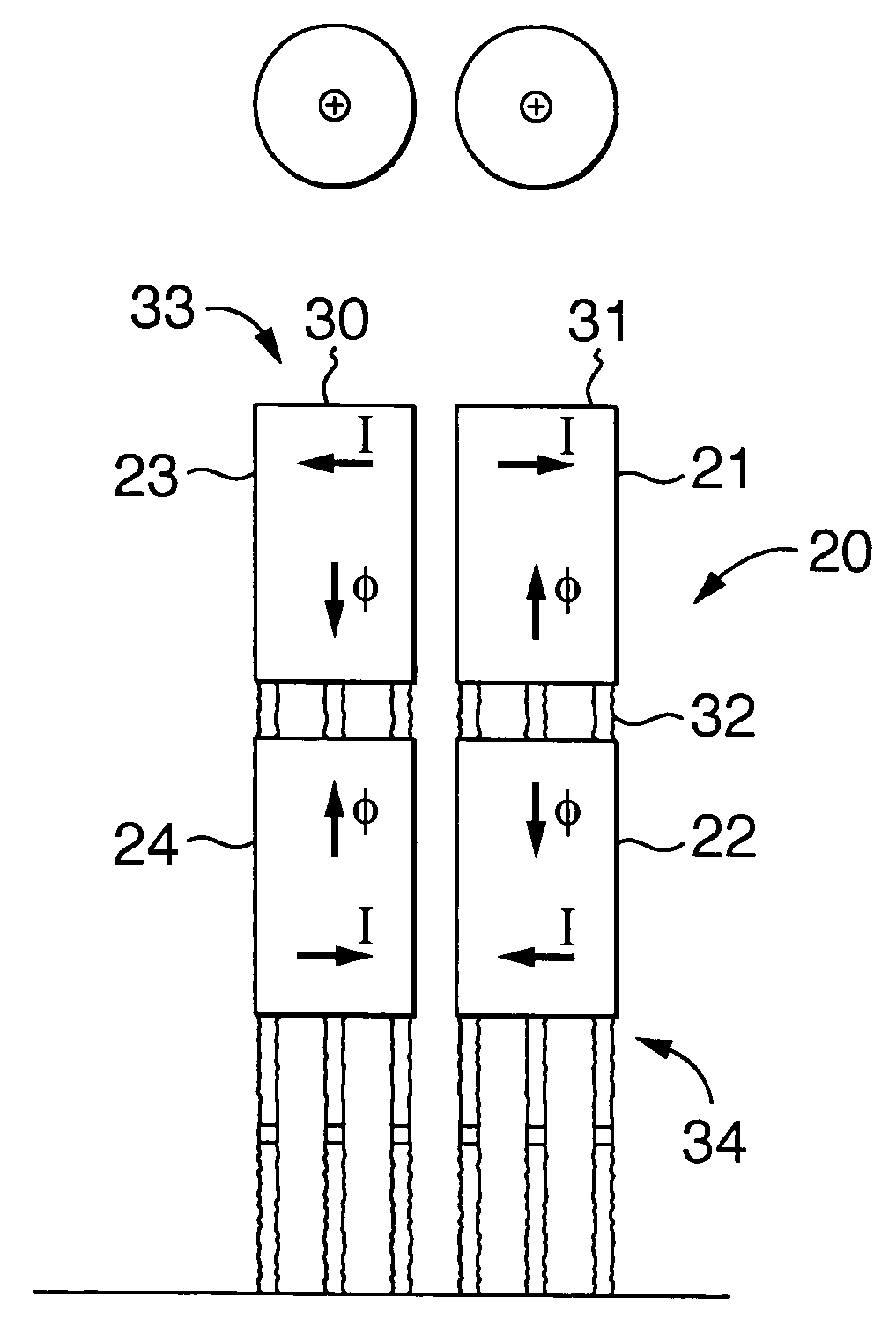
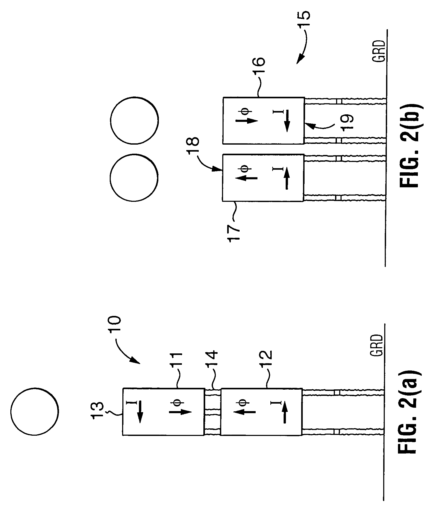
[0029]The present invention proposes that multiple coils per phase always be used when a substantial reduction in field strength is required in predetermined areas and configured geometrically and electrically in order to achieve the required reduction at lowest cost. Preferably, the coil multiples will be identical electrically but not necessaril...


PUM

PropertyMeasurementUnit
magnetic fieldaaaaaaaaaa
dipole momentsaaaaaaaaaa
voltageaaaaaaaaaa

Abstract

A method for reducing the magnetic field level in the vicinity of two or more connected reactors wherein each reactor is a magnetic dipole and wound so that currents flow in opposite directions and resulting in magnetic fluxes opposing each other.

Description

CROSS-REFERENCE TO RELATED APPLICATIONS[0001]Not ApplicableSTATEMENT REGARDING FEDERALLY SPONSORED RESEARCH OR DEVELOPMENT[0002]Not ApplicableREFERENCE TO A “SEQUENCE LISTING”[0003]Not ApplicableFIELD OF INVENTION[0004]The present invention relates to dry type air core system configuration, and more particularly to a method whereby a significant reduction in external magnetic field strength is achieved in a limited space.BACKGROUND OF INVENTION[0005]Although current research indicates that there are no biological risks associated with exposure to electromagnetic fields, the strategy of prudent avoidance is practical in terms of sitting exposure limits for the general public and even for workers in the electrical power sector. On this basis, exposure limits have been set for alternating power frequency magnetic fields. Air core reactors, like other power equipment (including transmission lines, etc.) are subject to these criteria.[0006]Current practice to achieve compliance is based ...

Claims


Application Information

Patent Timeline
Patent Type & Authority Patents(United States)
IPC IPC(8): H01H47/00H01F27/34H01F27/36H01F37/00
CPCH01F37/005H01F27/346
Inventor BURKE, PATRICK EARLDUDLEY, RICHARD FREDERICKMCLEAN, BARRY R.SHARP, MICHAEL RICHARD
Owner TRENCH
Why Eureka
Try Eureka