Data communication system, data receiving terminal and data sending terminal

a data communication system and data receiving technology, applied in the field of data communication system and data receiving and sending terminals, can solve the problems of increasing the reproduction delay time, reducing the sound, and reproducing sound, and achieve the effect of less sending delay

Inactive Publication Date: 2006-06-13
FUJITSU LTD
View PDF7 Cites 6 Cited by
  • Summary
  • Abstract
  • Description
  • Claims
  • Application Information

AI Technical Summary

Benefits of technology

[0031]With the foregoing conventional problems in view, a first object of the present invention is to provide a data communication system that realizes both reproduction of data with less sending delay and accumulation of high-quality data at a data receiving terminal.

Problems solved by technology

Particularly voice data must be sent without interruption; if an interruption occurs in received data, it results in reproduced sound with interruption so that the listener would feel an incompatibility.
However, when the network band is heavy in traffic as another data communication takes place using the same network 105, reduced sound would encounter an interruption at the receiving terminal unless the sending rate (sending data amount) of AV data is lowered, thus increasing the reproduction delay time by the interrupted time.
However, also this monitoring system occasionally encounters a problem in that the receiving terminal 104 accumulating the received data would become unable to receive data in the originally required quality if the sending quality is changed at the sending terminal 103 in conformity with the traffic of the above-mentioned network 105 in an effort to improve the reproduction delay time at the receiving terminal 104.
Since the above-mentioned resending control function is originally to request for resending quite the same packet as the lost packet in the occurrence of a packet loss, it is impossible to make a resending request in accordance with such quality change.

Method used


Image

  • Data communication system, data receiving terminal and data sending terminal
  • Data communication system, data receiving terminal and data sending terminal
  • Data communication system, data receiving terminal and data sending terminal

Examples


first embodiment

[0071](A) First Embodiment

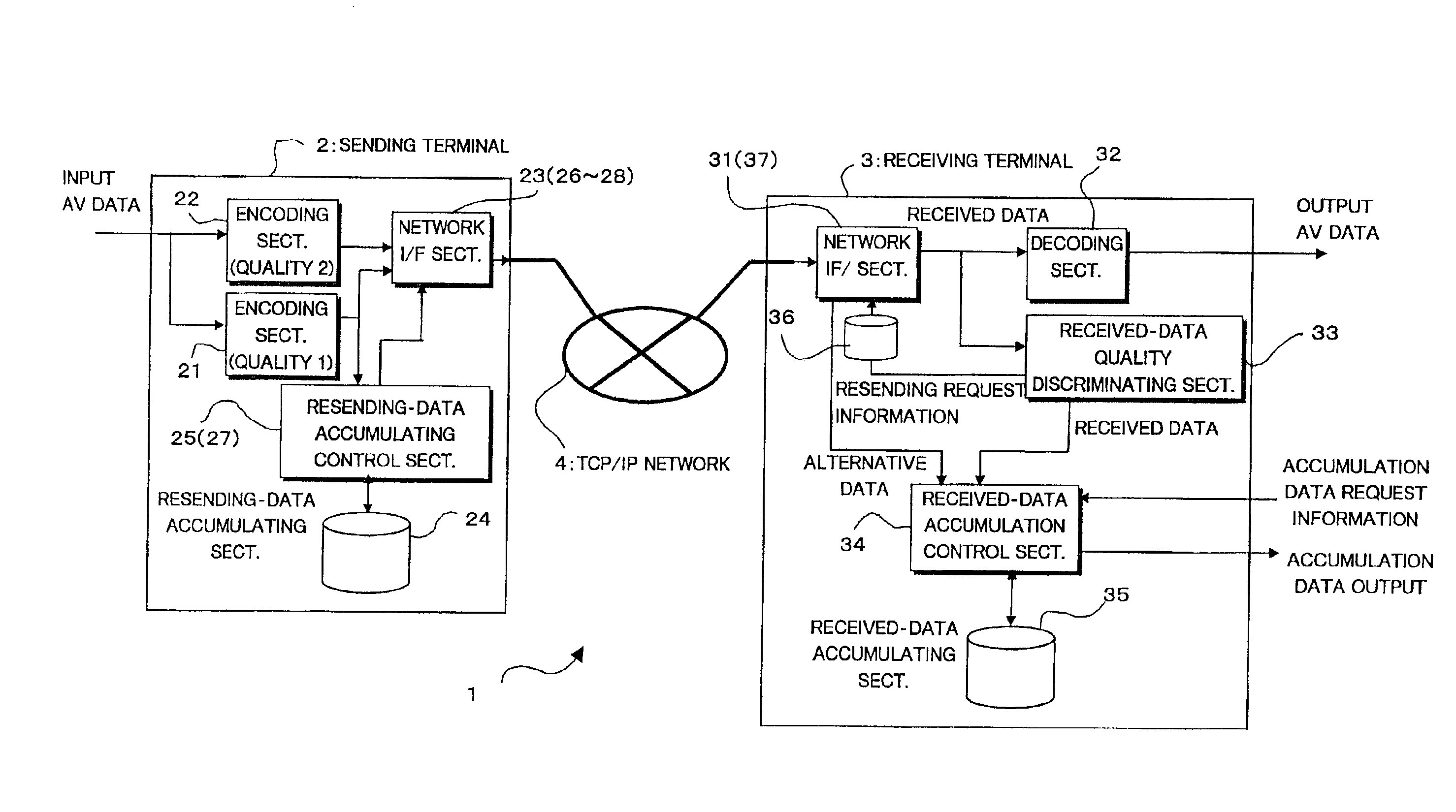
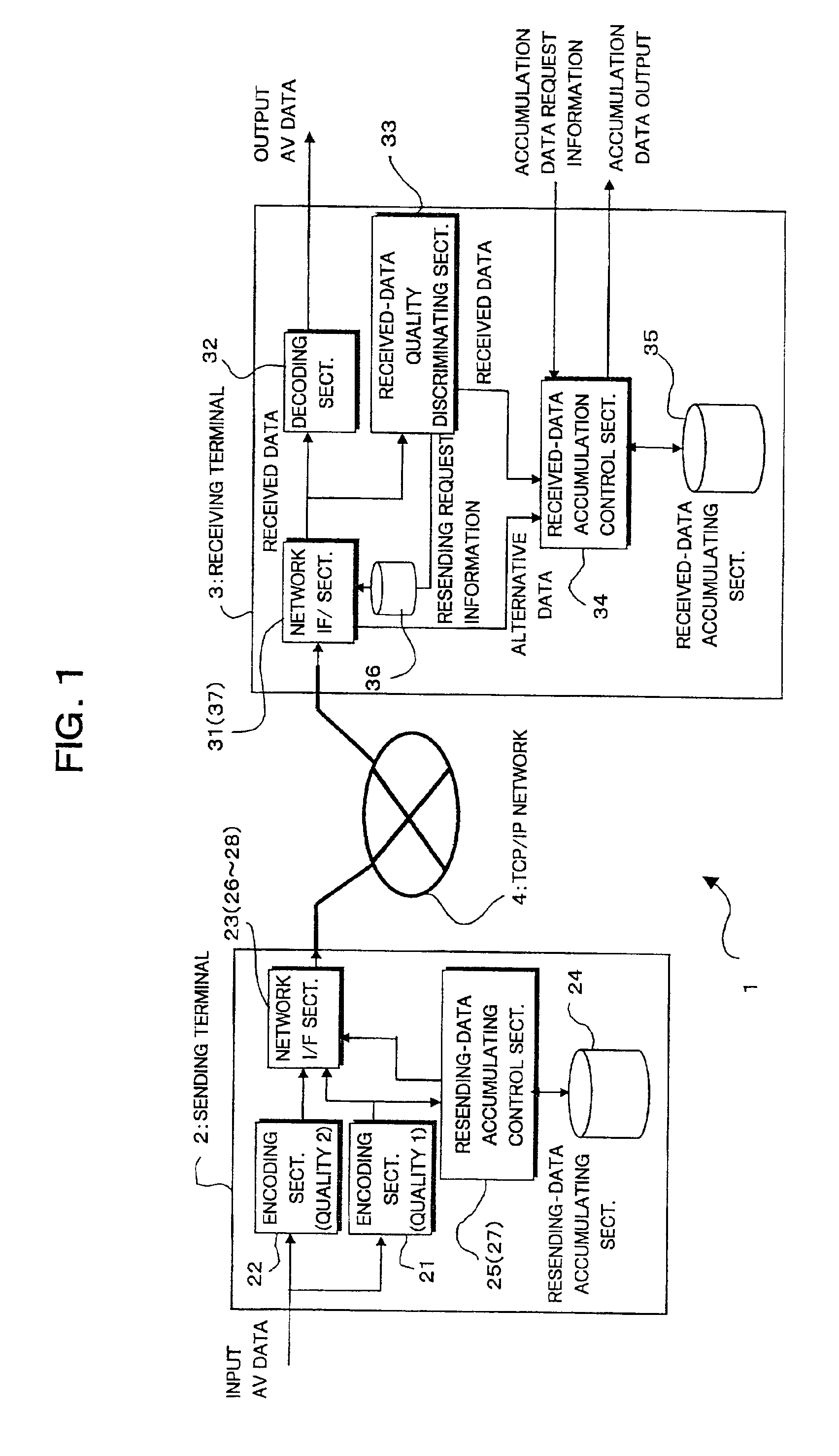
[0072]FIG. 1 is a block diagram showing a data communication system according to a first embodiment of the present invention. The data communication system 1 of FIG. 1 comprises data sending terminal (hereinafter also called the sending terminal) 2 and a data receiving terminal (hereinafter also called the receiving terminal) 3 communicably interconnected via a TCP / IP (transmission control protocol / internet protocol) network 4 identical with that described above in connection with FIG. 10.

[0073]In FIG. 1, the sending terminal 2 and the receiving terminal 3, only one each, are illustrated as connected to the TCP / IP network 4. Practically, however, a suitable number of each of the sending and receiving terminals 2, 3 are connected to the TCP / IP network 4 (hereinafter also called the network 4).

[0074]As a basic structure, shown in FIG. 1, the sending terminal 2 comprises first and second encoding sections 21, 22, a first network interface (I / F) section 23, a r...

second embodiment

[0124](B)

[0125]FIG. 6 is a block diagram showing another data communication system according to a second embodiment of the present invention. The data communication system 1A of FIG. 6 includes a sending terminal (data sending terminal) 5 and a receiving terminal (data receiving terminal) 6 which are mutually communicably interconnected via the same TCP / IP network 4 as described in connection with FIG. 10. Though illustration is omitted in FIG. 6, actually a suitable number of sending terminals 5 and a suitable number of receiving terminals 6 are connected to the TCP / IP network 4.

[0126]As shown in FIG. 6, the individual sending terminal 5 of the second embodiment is equipped with an encoding section 51, a network I / F section 52, a resending-data accumulation control section 53, and a resending-data accumulating section 54. And the individual receiving terminal 6 is equipped with a network I / F section 61, a decoding section 62, a received-data error detecting section 63, a received-d...


PUM


Abstract

At a data receiving terminal, if a received-data of a particular time section received from a data sending terminal does not satisfy a predetermined accumulation quality as the result of discrimination by a received-data quality discriminating section, an alternative-data sending requesting section requests a data sending terminal for alternative data satisfying the accumulation quality for the unsatisfied data of the particular time section. The result is that the data receiving terminal can realize both reproduction of data with less sending delay and accumulation of high-quality data.

Description

BACKGROUND OF THE INVENTION[0001]1. Field of the Invention[0002]The present invention relates to a data communication system and data receiving and sending terminals, and more particularly to a data communication system which enables real-time output and accumulation of received data concurrently at a data receiving terminal, and such data receiving and sending terminals.[0003]2. Description of Related Art[0004]FIG. 10 of the accompanying drawings is a block diagram showing a data communication system utilizing a TCP / IP (transmission control protocol / internet protocol). The data communication system 100 of FIG. 10 comprises a TCP / IP network 105, which is constructed by a plurality of communication networks 101 each according to TCP / IP and a plurality of routers 102, and a sending terminal 103 and a plurality of receiving terminals 104, which both terminals are connected to the TCP / IP network 105. For example, data of a particular service (e.g., VOD (video on demand)) can be delivere...

Claims


Application Information

Patent Timeline
Patent Type & Authority Patents(United States)
IPC IPC(8): H04L12/26G01R31/08H04N17/00G06F11/00G08C15/00H04J1/16H04J3/14H04L1/16H04L12/28H04L12/64H04L12/70H04N7/173H04N21/24H04N21/2662H04N21/442H04N21/6375
CPCH04L12/6418H04L2012/6475H04L2012/6472
Inventor WATANABE, HIDEAKIHAMANO, TAKASHI
Owner FUJITSU LTD
Why Eureka
Try Eureka