
Image generation device and image generation method

a technology of image generation device and image, which is applied in the direction of analog and hybrid computing, fluid pressure computing, instruments, etc., can solve the problems of less efficient use of memory, and achieve the effect of high speed and high quality rendering data

Active Publication Date: 2012-11-27
SONY COMPUTER ENTERTAINMENT INC
View PDF8 Cites 3 Cited by
  • Summary
  • Abstract
  • Description
  • Claims
  • Application Information

AI Technical Summary

Benefits of technology

[0006]In this background, a general purpose of the present invention is to provide an image generating apparatus and an image generating method capable of performing a graphic process efficiently in respect of storage capacity and volume of calculation.
[0013]According to the present invention, high-quality rendering data can be generated at a high speed.

Problems solved by technology

Then, the same palette is equally used for indexing of color values even in an area that need not be rendered in great detail, resulting in less efficient use of memory.

Method used


Image

  • Image generation device and image generation method
  • Image generation device and image generation method
  • Image generation device and image generation method

Examples


first embodiment

[0028

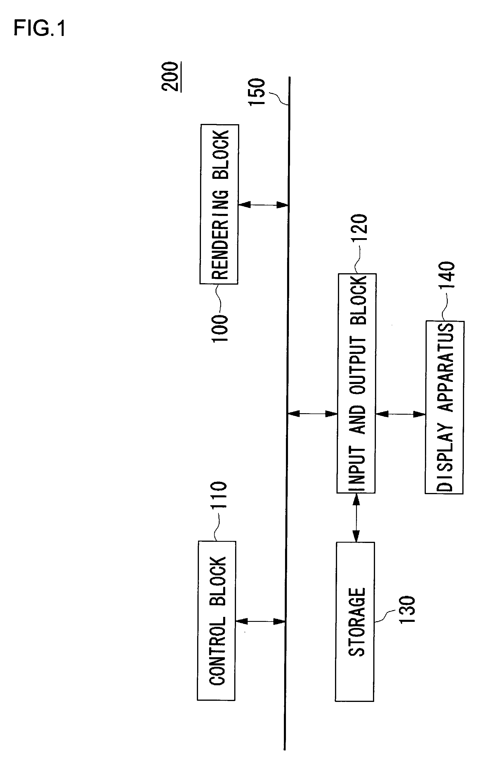
[0029]FIG. 1 shows the structure of an image generating apparatus 200 according to a first embodiment of the present invention. The image generating apparatus 200 is comprised of a rendering block 100, a control block 110 and an input and output block 120 connected to each other via a bus 150. A storage apparatus 130 and a display apparatus 140 are connected to the input and output block 120. The input and output block 120 may communicate with another apparatus via a network so as to import data necessary for rendering from an external source.

[0030]The control block 110 is a block that controls the entirety of the image generating apparatus 200. The control block 100 manages synchronization of data transfer between the interior of the image generating apparatus 200 and peripheral apparatuses such as the storage apparatus 130 and the display apparatus 140. The control block 110 is also responsible for processing interrupts from the individual units in the image generating appara...


PUM


Abstract

A calculation unit (58) references texture data (62) in a storage unit (60) and acquires texel information of index color formal An integral look-up table (64) has a structure containing a plurality of color look-up tables based on the detail degree (LOD) of the area to be plotted A look-up table reference unit (70) selectively references the color look-up table based on the LOD stored in the integral look-up table (64) according to the LOD value of the texel obtained by the LOD calculation unit (68), acquires color information corresponding to the index value of the texel, and outputs it to the calculation unit (58). The calculation unit (58) performs filter processing such as bi-linear interpolation according to the texel color information and outputs the texel information after the processing.

Description

[0001]This application is a National Phase Application of International Application No. PCT / JP2005 / 007137, filed Apr. 13, 2005, which claims the benefit under 35 U.S.C. 119 (a-e) of Japanese Application No. 2004-118328 filed Apr. 13, 2004, which is herein incorporated by reference.TECHNICAL FIELD[0002]The present invention relates to an image generating apparatus and an image generating method for generating image data.BACKGROUND TECHNOLOGY[0003]In 3D computer graphics, a polygon model, in which 3D objects are generally represented by a larger number of polygons, is employed. In rendering objects using a polygon model, shading is performed in which the surface of polygons are shaded in consideration of light sources, view points and the reflectivity of objects' surfaces. In order to generate a photorealistic image, texture mapping, in which a texture image is mapped to the surface of polygon model, is performed.[0004]In order to reduce the volume of data for texture images, the inde...

Claims


Application Information

Patent Timeline
Patent Type & Authority Patents(United States)
IPC IPC(8): G09G5/02G06G5/00G06T15/04
CPCG06T15/04
Inventor KOGUCHI, TAKAHIROTAKAMA, NORIO
Owner SONY COMPUTER ENTERTAINMENT INC
Learn More