Source synchronous link with clock recovery and bit skew alignment

a synchronous link and source technology, applied in the field of high-speed data transmission, can solve the problems of high cost, disadvantage, precise clock and timing requirements, etc., and achieve the effect of improving the density of links and efficient data transmission

Active Publication Date: 2006-06-13
JUMIPER NETWORKS INC
View PDF12 Cites 27 Cited by
  • Summary
  • Abstract
  • Description
  • Claims
  • Application Information

AI Technical Summary

Problems solved by technology

Although synchronous data transfer has many advantages, the precise clocks and timing requirements are very costly.
Therefore, conventional synchronous and asynchronous data transmission systems each have disadvantageous.

Method used


Image

  • Source synchronous link with clock recovery and bit skew alignment
  • Source synchronous link with clock recovery and bit skew alignment
  • Source synchronous link with clock recovery and bit skew alignment

Examples


Embodiment Construction

[0021]The following detailed description of the invention refers to the accompanying drawings. The same reference numbers are sometimes used in different drawings to identify the same or similar elements. Also, the following detailed description does not limit the invention. Instead, the scope of the invention is defined by the appended claims and equivalents of the claim limitations.

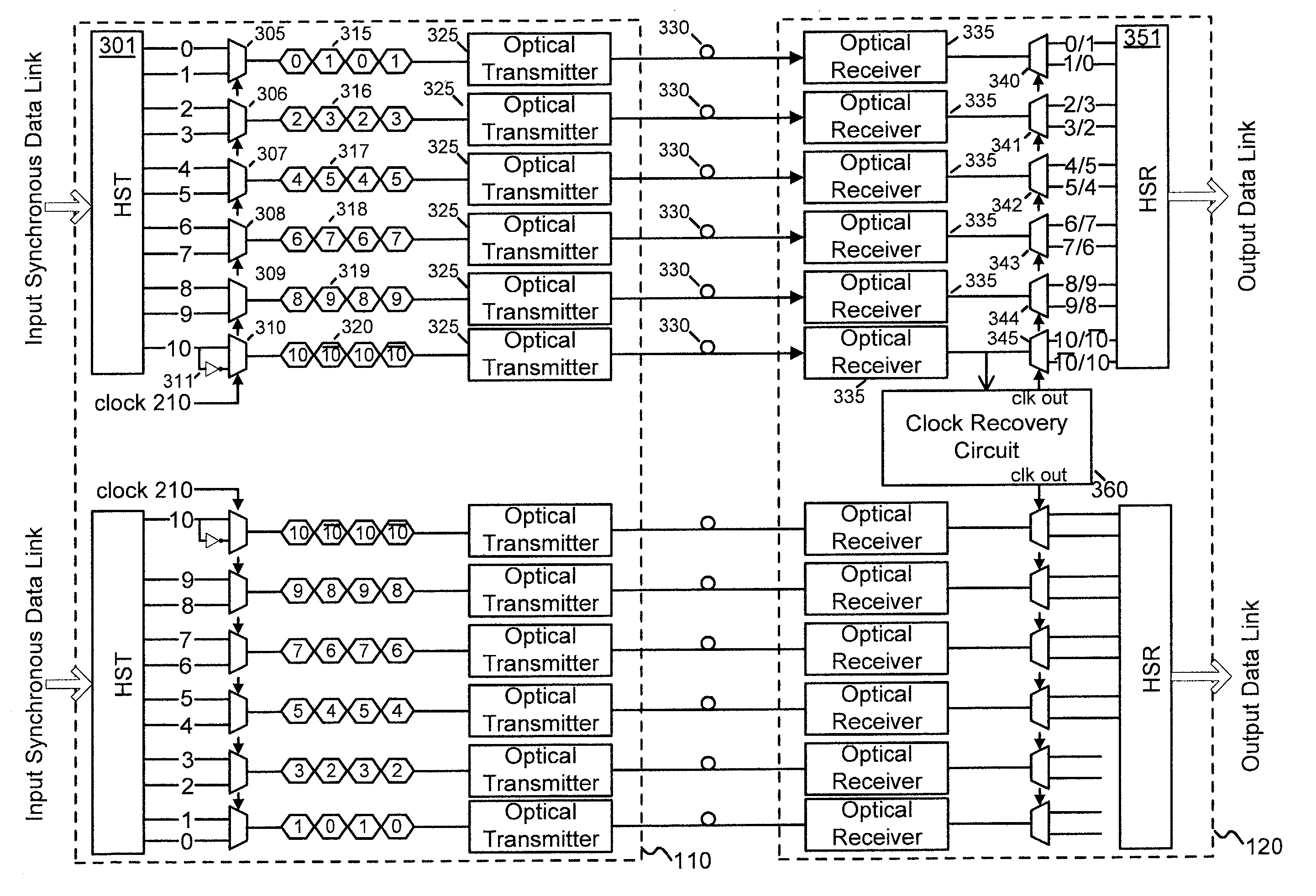
[0022]As described herein, a transmission system converts a plurality of synchronous signals for transmission onto a physical link. In one embodiment, transmission bandwidth is increased by embedding a clock signal in the converted signals.

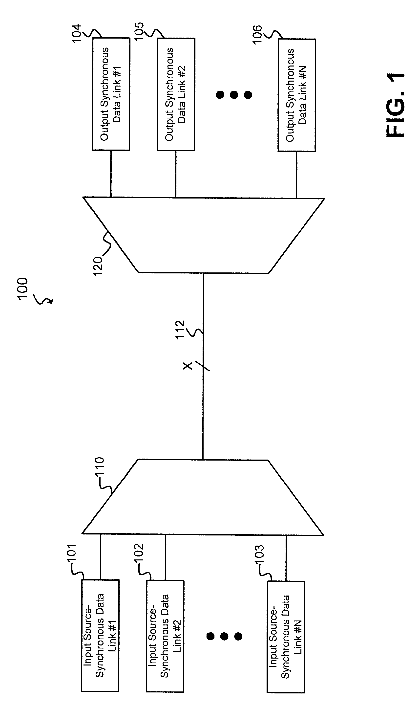
[0023]FIG. 1 is a block diagram illustrating a data transmission system 100 consistent with the principles of the invention. Data transmission system 100 includes N input synchronous data links 101–103, a multiplexing unit 110, a link 112, a demultiplexing unit 120, and N output synchronous data links 104–106. Each data link 101–103 may carry data signals transmitted ...


PUM


Abstract

A high speed transmission system transfers data streams over a plurality of data links. Each data link may carry a number of bit streams. On the transmitting end, multiplexers serialize the bit streams, which are then transmitted to the receiving end. A clock signal is not transmitted over the optical link. Instead, an indication of the appropriate clock signal frequency and phase is embedded in the transmitted data. At the receiving end, a clock recovery circuit generates a clock signal of an appropriate frequency and phase based on the embedded indication. The new clock signal is used to sample and reconstruct the original data streams.

Description

BACKGROUND OF THE INVENTION[0001]A. Field of the Invention[0002]The present invention relates generally to high-speed data transmission, and more particularly, to a source synchronous data transmission link.[0003]B. Description of Related Art[0004]Conventional communication systems typically use either synchronous or asynchronous data transmission to transmit data from a transmitting system to a receiving system. Synchronous data transmission requires the transmitting and receiving systems to be synchronized with each other.[0005]Conventional synchronous data transfer has the characteristic of requiring relatively constant time periods between successive events. Keeping time periods relatively constant, such as the time between successive bits, allows end systems to stay synchronized because the timing of successive events is predetermined.[0006]To implement synchronous data transfer, the transmitting and receiving systems can be synchronized in a variety of ways. In some synchronou...

Claims


Application Information

Patent Timeline
Patent Type & Authority Patents(United States)
IPC IPC(8): H04J3/06
CPCH04L25/14H04L7/0066H04L7/033
Inventor CHENGSON, DAVIDDARNAUER, JOEL FREDERICKTUCKER, MATTHEW A.
Owner JUMIPER NETWORKS INC
Why Eureka
Try Eureka