
Process cartridge remanufacturing method

a technology of process cartridges and manufacturing methods, applied in electrographic process equipment, instruments, optics, etc., can solve the problems of losing the commercial value of the process cartridge, and achieve the effect of preventing leakag

Inactive Publication Date: 2006-06-13
CANON KK
View PDF11 Cites 13 Cited by
  • Summary
  • Abstract
  • Description
  • Claims
  • Application Information

AI Technical Summary

Benefits of technology

[0008]It is another object of the present invention to provide a remanufacturing method of a process cartridge in which when the process cartridge is transported, the toner is prevented from leaking out.
[0009]It is a further object of the present invention to provide a remanufacturing method of a process cartridge for recycling a process cartridge whose toner has been consumed to such an extent that the user is not satisfied with the image quality so that the used-up cartridge can be given commercial value.

Problems solved by technology

When the toner is consumed up to such an extent that user is not satisfied with the image quality, the commercial value of the process cartridge is lost.

Method used


Image

  • Process cartridge remanufacturing method
  • Process cartridge remanufacturing method
  • Process cartridge remanufacturing method

Examples


embodiment 1

(Separating Step Between Toner Developing Container and Cleaner Container)

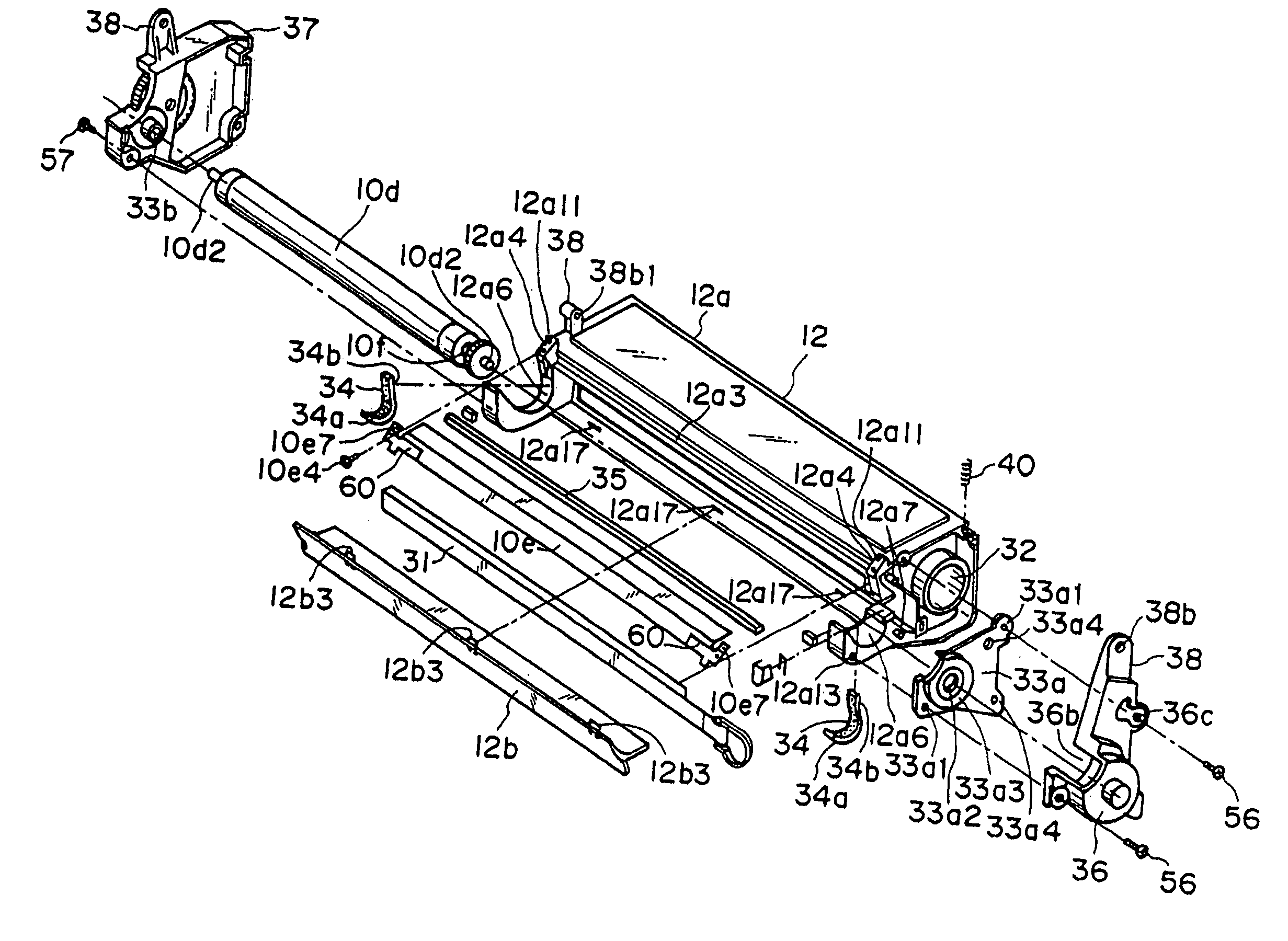
[0162]The tension coil spring 59 shown in FIG. 7 is disengaged from the spring hook 13p of the cleaner container 13.

[0163]By doing so, the force between the photosensitive drum 7 and the developing roller 10d is provided only by the compression coil spring 40. Therefore, the toner developing container 12 and the cleaner container 13 are rotatable relative to each other about the pin 41.

[0164]Then, the pin 41 is removed. This is done by pulling out the pin 41 using a plyer or the like if the pin 41 is projected out of the process cartridge B. If not, the pin 41 is pushed into the process cartridge to disengage it.

[0165]Thus, the container separating step is completed, by which the toner developing container 12 comprising the toner accommodating portion 10a, the toner supply opening 12a1, the developing roller 10d and the developing blade 10e, and the cleaner container 13 comprising the photosensitive drum 7, ar...


PUM


Abstract

A remanufacturing method of remanufacting a process cartridge includes (a) a step of preparing a used process cartridge which comprises a toner developing container, a cleaning container and pins for coupling the toner developing container and the cleaning container at opposite longitudinal ends of the process cartridge; the toner developing container including a toner accommodating portion, a toner supply opening, a developing roller and a developing blade; the cleaning container including an electrophotographic photosensitive drum; (b) a container separating step of separating the process cartridge into the toner developing container and the developing container by disengaging the pins from the process cartridge; (c) a developing roller dismounting step of dismounting the developing roller from the toner developing container separated by the container separating step; (d) a developing blade dismounting step of dismounting the developing blade from the toner developing container separated by the container separating step; (e) an elastic member mounting step of mounting an elastic member to a longitudinally inside of an end seal provided adjacent each of opposite longitudinal ends of a or the developing roller, at a position laterally outside of the end seal; (f) a developing blade mounting step of mounting a or the developing blade on a or the toner developer container; (g) a developing roller mounting step of mounting a or the developing roller on the toner developer container having the developing blade; (h) a toner refilling step of refilling the toner into a or the toner accommodating portion of the toner developing container having the developing blade and the developing roller; and (i) a container coupling step of coupling the toner developing container having the developing blade and the developing roller with a or the cleaning container by engaging a or the pin into them.

Description

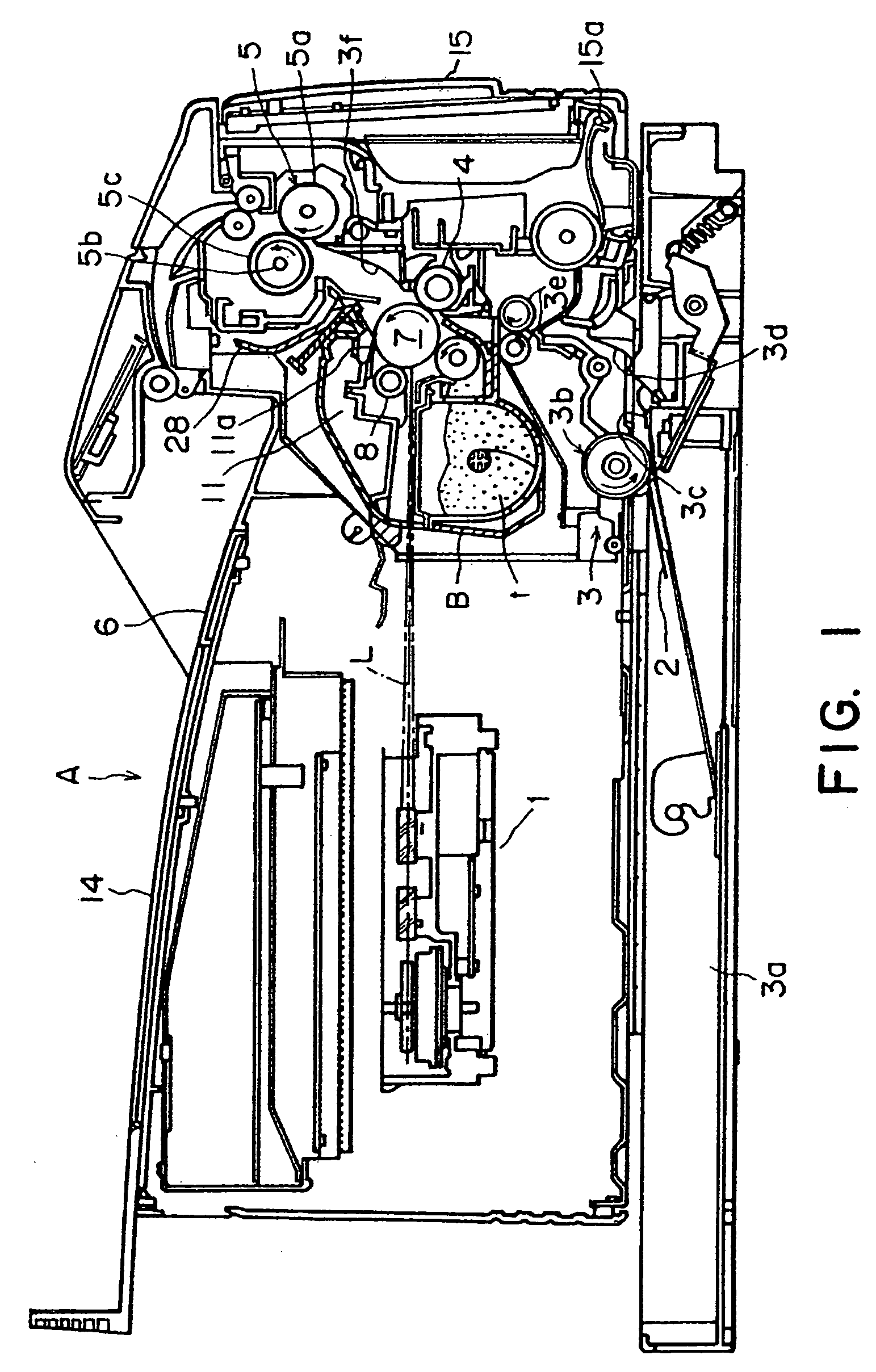
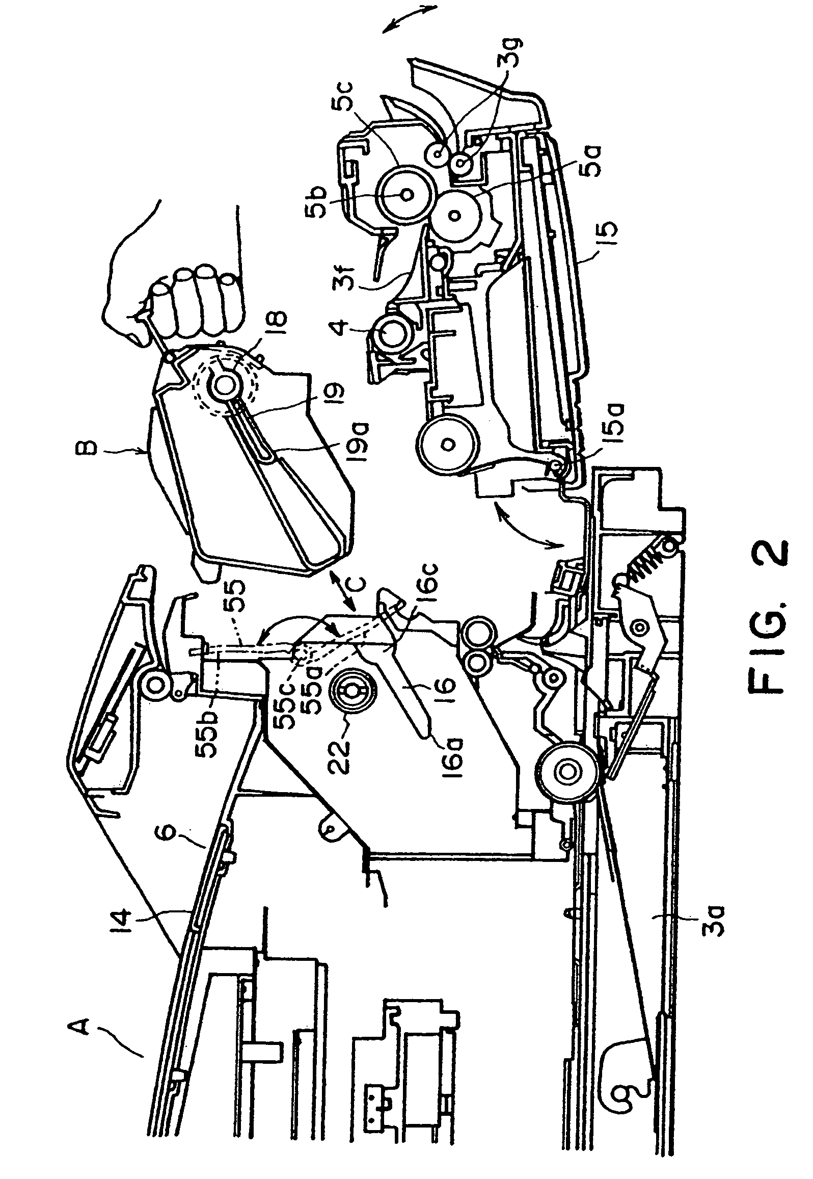
FIELD OF THE INVENTION AND RELATED ART[0001]The present invention relates to a remanufacturing method for a process cartridge.[0002]Here, the process cartridge is a cartridge containing at least a developing roller as developing means and an electrophotographic photosensitive member as a unit, the cartridge being detachably mountable to a main assembly of an electrophotographic image forming apparatus.[0003]The electrophotographic image forming apparatus is an apparatus in which an image is formed on a recording material (recording paper, textile or the like) using an electrophotographic image forming process, and includes an electrophotographic copying machine, an electrophotographic printer (an LED printer, a laser beam printer and so on, an electrophotographic printer-type facsimile machine, an electrophotographic word processor and the like).[0004]In an electrophotographic image forming apparatus using an electrophotographic image forming process, a process cartridge is used whi...

Claims


Application Information

Patent Timeline
Patent Type & Authority Patents(United States)
IPC IPC(8): G03G15/00G03G15/08G03G21/18
CPCG03G21/181G03G21/1832G03G2215/00987G03G21/18
Inventor HIGETA, AKIRAKAKUMI, YOSHIYUKI
Owner CANON KK
Learn More